
Intake air cooling apparatus abnormality detection system for internal combustion engine

a cooling apparatus and abnormal detection technology, applied in the direction of machines/engines, combustion-air/fuel-air treatment, electric control, etc., can solve the problems of thermal damage to a component, abnormality may not be detected, etc., to reliably detect abnormalities and accurately determine the load state of the internal combustion engine

Active Publication Date: 2021-02-09
HONDA MOTOR CO LTD
View PDF11 Cites 1 Cited by
  • Summary
  • Abstract
  • Description
  • Claims
  • Application Information

AI Technical Summary

Benefits of technology

[0010]Accordingly, when the internal combustion engine is in the high load state even if a characteristic abnormality occurs in one of the intake air temperature sensors, it is possible to reliably determine that an abnormality occurs in the intake air cooling apparatus without delay.
[0016]The degree of supercharge is increased as the pressure difference between the atmospheric pressure and the pressure in the intake manifold is increased. Since the intake air temperature is rapidly increased at this time, it is preferred that the abnormality in the intake air cooling apparatus be rapidly detected. Accordingly, according to the intake air cooling apparatus abnormality detection system in (3), shortening the certain time before it is determined that an abnormality occurs in the intake air cooling apparatus in accordance with the supercharge state by the supercharger enables the abnormality in the intake air cooling apparatus to be more appropriately detected.
[0018]In the intake air cooling apparatus abnormality detection system in (4), if it is determined that an abnormality occurs in the intake air cooling apparatus, the supercharge stop request signal for requesting the supercharger to stop the supercharge is output. Accordingly, it is possible to prevent thermal damage to the intake valve or the like even if a characteristics abnormality occurs in one of the intake air temperature sensors.
[0020]In the intake air cooling apparatus abnormality detection system in (5), the load state determination unit determines that the internal combustion engine is in the certain load state in the state in which the pressure difference between the atmospheric pressure and the pressure in the intake manifold is greater than a predetermined value and / or in the state in which the position of the intake valve is greater than a predetermined position. Accordingly, it is possible to accurately determine the load state of the internal combustion engine.
[0021]According to the present disclosure, it is possible to provide an intake air cooling apparatus abnormality detection system for an internal combustion engine, which is capable of reliably detecting an abnormality in an intake air cooling apparatus without delay even if a characteristic abnormality occurs in an intake air temperature sensor.

Problems solved by technology

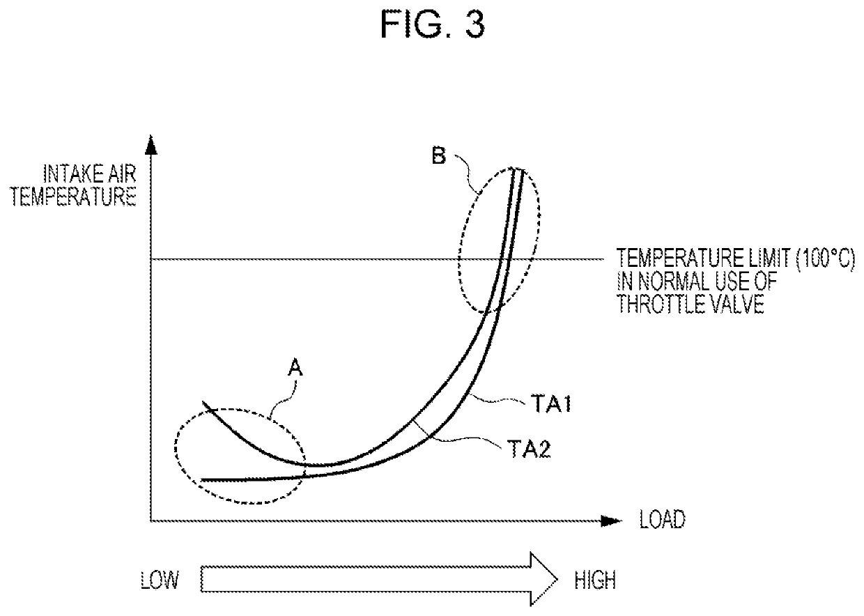
However, in the case of the system that detects an abnormality in the intake air cooling apparatus including the intercooler of the internal combustion engine based on one intake air temperature sensor provided on the intake path of the internal combustion engine, if a characteristic abnormality (for example, a shift of a zero point due to deterioration or abnormal correlation between actual temperatures and an output from the sensor) occurs in the intake air temperature sensor, the abnormality may not be detected in spite of the temperature at which the abnormality should be practically detected.
For example, when the threshold value of the temperature at which an abnormality in the intake air cooling apparatus is detected is set to 100° C. and the value detected by the intake air temperature sensor is shifted from the actual temperature by −20° C. due to the characteristic abnormality, there is a problem in that the value detected by the intake air temperature sensor is 90° C. even when the actual temperature is 110° C. and the abnormality in the intake air cooling apparatus is not detected.
When the abnormality in the intake air cooling apparatus is not appropriately detected, particularly when the engine the intake air temperature of which is increased is in a high load state, thermal damage may occur in a component, such as a throttle valve, provided on the intake path of the internal combustion engine.

Method used


Image

  • Intake air cooling apparatus abnormality detection system for internal combustion engine
  • Intake air cooling apparatus abnormality detection system for internal combustion engine
  • Intake air cooling apparatus abnormality detection system for internal combustion engine

Examples


first embodiment

[0028]A first embodiment of the present disclosure will herein be described in detail with reference to the drawings.

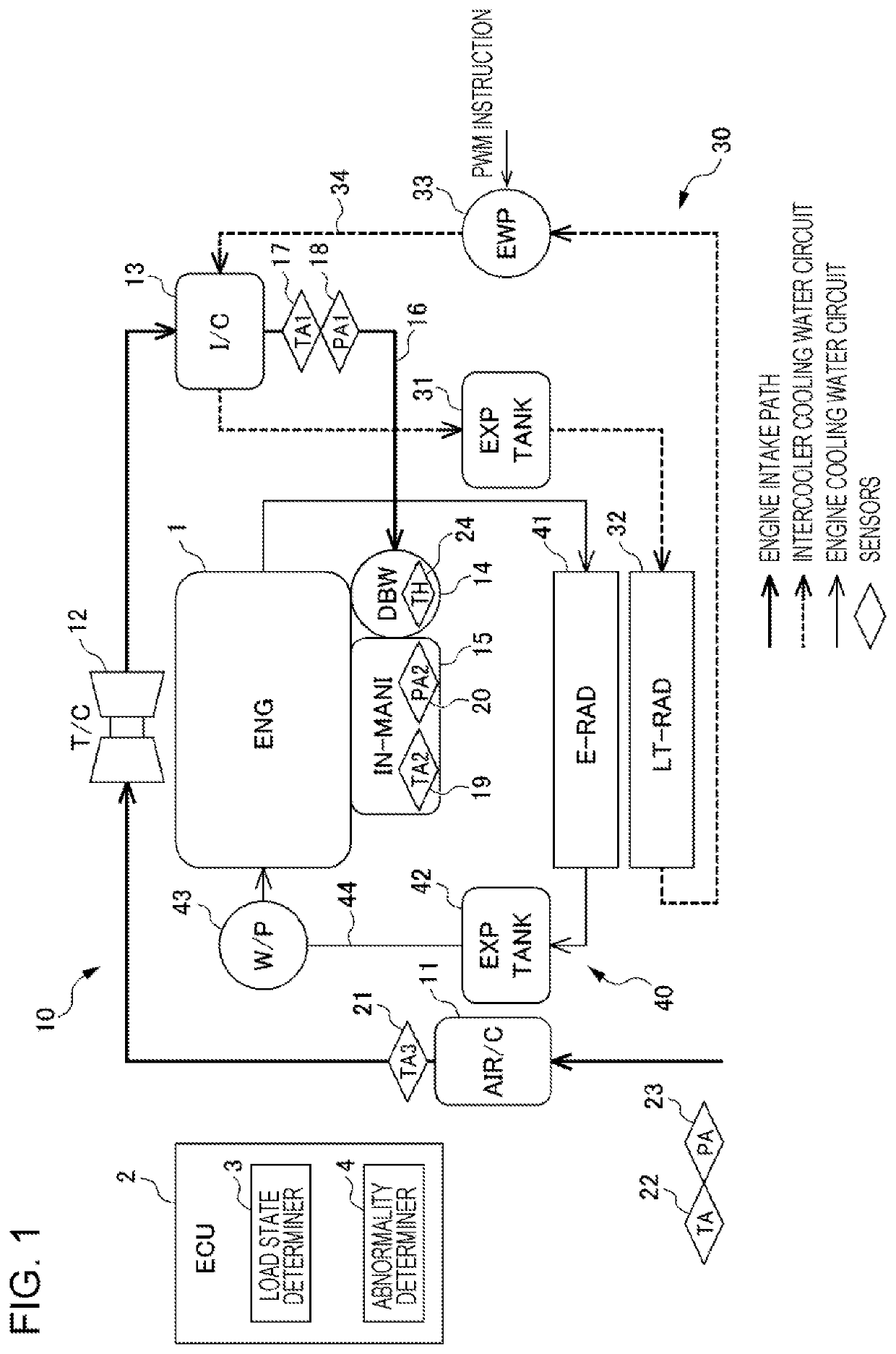
[0029]FIG. 1 illustrates an exemplary configuration of an engine 1 serving as an internal combustion engine, an engine intake path 10, an intercooler cooling water circuit 30 serving as an intake air cooling apparatus, an engine cooling water circuit 40, and an electronic control unit (ECU) 2 controlling the above components, according to the first embodiment.

[0030]The engine 1 is a gasoline engine that directly injects fuel into a combustion chamber of each cylinder (not illustrated). A fuel injection valve (not illustrated) is provided for each cylinder. The opening times and the closing times of the fuel injection valves are controlled by the ECU 2. The ECU 2 also controls, for example, a turbo charger 12 and a throttle valve 14 on the engine intake path described below.

[0031]The engine intake path 10 is coupled at the upstream side of the engine 1. On the engine i...

second embodiment

[0098]An intake air cooling apparatus abnormality detection system according to a second embodiment of the present disclosure will herein be described in detail with reference to the drawings. The same reference numerals are used in the second embodiment to identify the same components in the first embodiment. A description of such components is omitted herein.

[0099]FIG. 5 is a flowchart in the second embodiment.

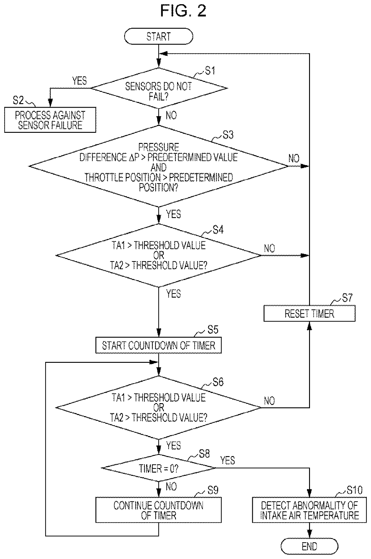
[0100]In the second embodiment, as illustrated in FIG. 5, Step 11 for setting the timer is inserted between Step S4 and Step S5 in the flowchart in the first embodiment illustrated in FIG. 2.

[0101]In general, the intake air temperature is rapidly increased as the degree of supercharge by the turbo charger 12 is increased. Accordingly, it is preferred that an abnormality in the intercooler cooling water circuit 30 be rapidly detected as the degree of supercharge by the turbo charger 12 is higher.

[0102]The pressure difference ΔP between the atmospheric pressure PA and the pres...


PUM


Abstract

An intake air cooling apparatus abnormality detection system for an engine includes a first intake air temperature sensor that detects an intake air temperature in an intake pipe at the downstream side of an intercooler and a second intake air temperature sensor that detects the intake air temperature in an intake manifold. An abnormality determination unit determines that an abnormality occurs in an intercooler cooling water circuit if a state in which at least one of a value based on an output from the first intake air temperature sensor and a value based on an output from the second intake air temperature sensor exceeds a predetermined threshold value continues for a certain time or longer when a load state determination unit determines that the engine is in a high load state.

Description

CROSS REFERENCES TO RELATED APPLICATIONS[0001]The present application claims priority under 35 U.S.C. § 119 to Japanese Patent Application No. 2018-084020, filed Apr. 25, 2018, entitled “Intake Air Cooling Apparatus Abnormality Detection System for Internal Combustion Engine.” The contents of this application are incorporated herein by reference in their entirety.BACKGROUND1. Field[0002]The present disclosure relates to an intake air cooling apparatus abnormality detection system for an internal combustion engine. Specifically, the present disclosure relates to a system that detects an abnormality in an intake air cooling apparatus in an internal combustion engine based on outputs from intake air temperature sensors provided on an intake path of the internal combustion engine. internal combustion engine2. Description of the Related Art[0003]Systems have hitherto been known, which compress air with superchargers and supply the compressed supercharged air to internal combustion engine...

Claims


Application Information

Patent Timeline
Patent Type & Authority Patents(United States)
IPC IPC(8): F02D41/00F02D41/14F01P11/16F02B37/12
CPCF02D41/1495F01P11/16F02B37/12F02D41/0002F02D41/144F02B77/08F02M35/10157F02M35/1038F01P11/14F01P2060/02F02B29/0443F02D41/0007F02D41/22F02D41/2403F02D2200/0402F02D2200/0404F02D2200/0406F02D2200/0414Y02T10/12Y02T10/40
Inventor ISHIMASA, JYODAICHO, HISASHI
Owner HONDA MOTOR CO LTD
Learn More