Check patentability & draft patents in minutes with Patsnap Eureka AI!

Process for catalyst deactivation

a technology of olefin polymerisation and catalyst, which is applied in the direction of chemical recycling, etc., can solve the problems of non-consumable catalyst, poor catalyst quality, and high cost of catalyst deactivation

Active Publication Date: 2021-04-20
BOREALIS AG
View PDF89 Cites 0 Cited by
  • Summary
  • Abstract
  • Description
  • Claims
  • Application Information

AI Technical Summary

Benefits of technology

This method allows for safe and efficient deactivation of catalysts without foaming or gas formation, ensuring complete inactivation of catalysts, even at significant concentrations, and is suitable for industrial-scale applications.

Problems solved by technology

Many such catalysts are pyrophoric, igniting on contact with air and / or moisture, whereby the handling of the catalyst requires extra caution and strict safety rules.
Such reasons include poor catalyst quality, non-consumed catalyst in the polymerisation process or remaining active catalyst residues in reactors.
However, deactivating the catalyst in a safe, and quick manner without causing any new issues to arise, is demanding.
For example, side-reactions and / or foam or gas formation are a serious risk during the deactivation process.
However, such reactions might happen violently.
Although resulting in basically inert catalyst substances, this kind of reaction is inherently dangerous, especially on an industrial scale.
Also, such reactions between the catalyst and deactivation medium can form non-desired gases or foam formation.
Alternatively, between some deactivation media and the catalyst, the reaction may happen slowly, and might even be incomplete.
This means that the catalyst can remain active and in a hazardous condition even after a long time period.
This poses a rather different problem from simply deactivating any residual impurity in a reactor or any residual impurity in a polymer mass.
This is also a different problem from deactivation within a reactor where again catalyst concentrations are low as there are other reactants, diluent, solvent etc present.
In particular, there is a problem of foaming.
It also possible that some un-used catalyst, due to several reasons, like quality problems, is to be deactivated.
The routine laboratory method for passivating a catalyst waste uses IPA but the inventors found that the use of this compound cannot be upscaled due to evolution of methane gas, which results in a terrible foaming on an industrial scale resulting in an incomplete deactivation and operational problems associated with foaming.

Method used


Image

  • Process for catalyst deactivation

Examples


##ventive example 1

Inventive Example 1

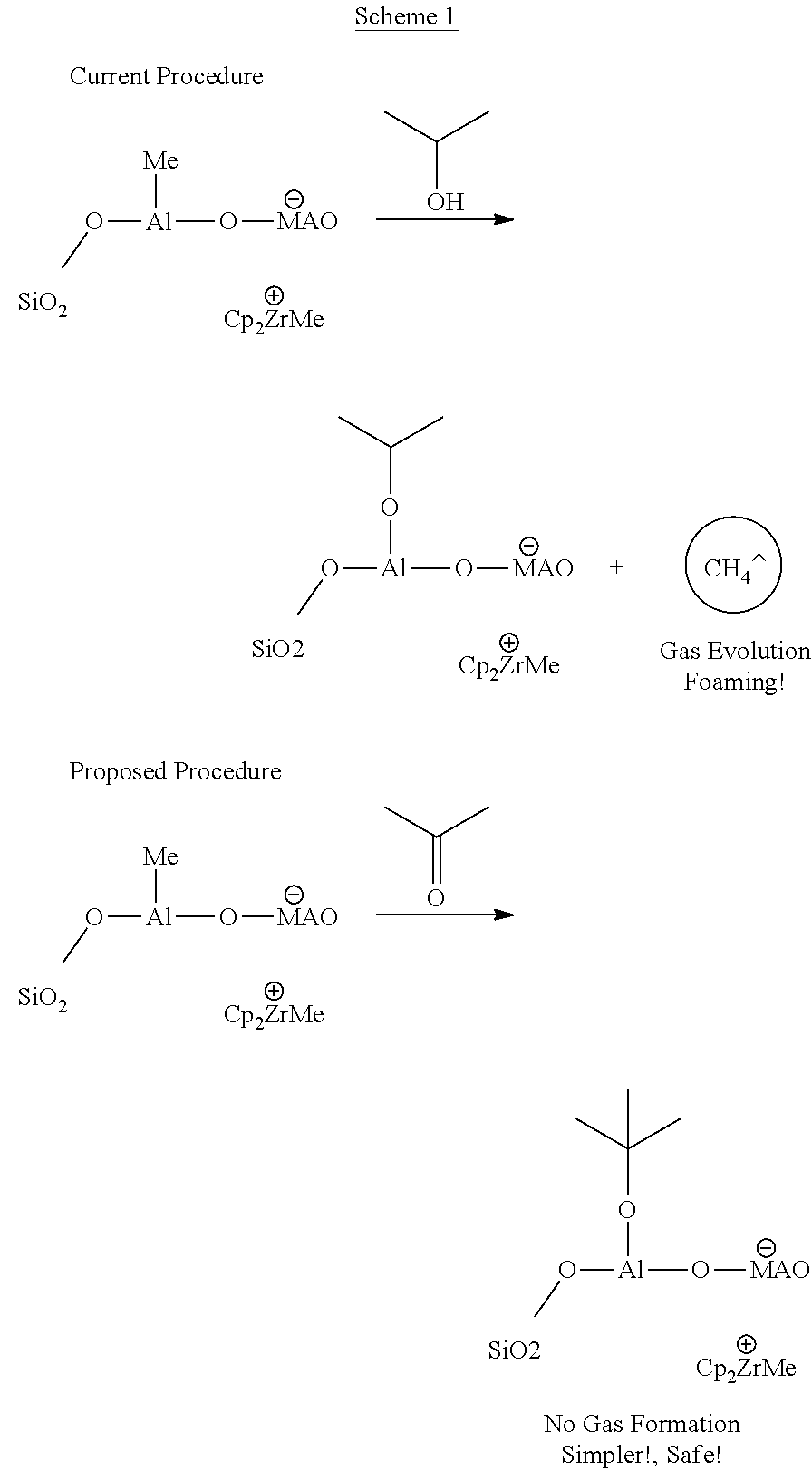
[0156]Comparative exmple 1 was repeated but with 2.0 g of acetone instead of IPA. Treatment with acetone resulted in minimal foaming. The inventors consider that any foaming is likely due to impurity, e.g. from the residual presence of moisture, IPA or phenol in the catalyst or in the technical grade acetone. The reaction volume did not increase significantly as was the case with IPA.

[0157]The residual activity after treatment with acetone was monitored after every 30 minutes by withdrawing a small portion of the reaction mixture and testing it by contacting with water (2.0 mL). No violent reaction was observed after 2 h on contact with water.

##ventive example 2

Inventive Example 2

[0165]A 10 wt % catalyst oil slurry was prepared as in comparative example 2. Reactor jacket temp was set to 20° C. Addition of acetone was started as 50 ml portions. It was immediately observed that there was less foaming and therefore 800 ml acetone could be added within 70 min into reactor (acetone / Al=2.2 mol / mol).

[0166]Temperature in the reactor was increased ˜1° C. during acetone addition. Catalyst / oil / acetone mixture was mixed over the weekend before the first sampling after 3 days.

[0167]Activity test (40 ml sample+10 ml water) was stable compared to the comparative example 2. Passivation of the mixture in the reactor was continued and 630 ml acetone was added into the reactor. The total amount of acetone added was thus 1430 ml. The final acetone / Al mol / mol ratio was ˜4. Deactivation was deemed complete.

[0168]In order to remove the deactivation agent, reactor oil circulation temperature was increased to 80° C. and nitrogen was fed 0.5 kg / h via the vessel bot...


PUM

PropertyMeasurementUnit
temperatureaaaaaaaaaa

Abstract

A process for the offline deactivation of at least one single site catalyst comprising contacting said catalyst with a deactivating agent selected from an aprotic low molecular weight carbonyl group containing organic compound or an aprotic low molecular weight orthoester or an aprotic low molecular weight acetal compound.

Description

CROSS-REFERENCE TO RELATED APPLICATIONS[0001]This application is a national stage application filed under 35 U.S.C. § 371 of PCT / EP2017 / 065395 filed Jun. 22, 2017, which claims the benefit of priority to European Application No. 16175998.0 filed Jun. 23, 2016, both of which are hereby incorporated herein by reference in their entireties.FIELD OF INVENTION[0002]The present invention relates to a method for deactivation of an olefin polymerisation catalyst. More specifically, the present invention concerns a method for deactivating catalysts comprising a transition metal of Group 3 to 10 and an aluminum cocatalyst, especially single site catalysts, using a carbonyl (C═O) group containing, aprotic low molecular weight organic compound which is capable of deactivating the catalyst without non-desired side reactions.BACKGROUND[0003]Polyolefins such as polyethylene, polypropylene and copolymers thereof with other α-olefins are typically produced in the presence of transition metal catalys...

Claims


Application Information

Patent Timeline
Patent Type & Authority Patents(United States)
IPC IPC(8): C08F2/00C08F2/38C08F4/6592C08F6/02C08F2/06
CPCC08F6/02C08F2/06C08F2/38C08F4/65925C08F2410/05C08F4/65912C08F4/65916C08F10/00
Inventor SAEED, IRFANNIKKILÄ, KATRIKALLIO, KALLE
Owner BOREALIS AG
Features
  • R&D
  • Intellectual Property
  • Life Sciences
  • Materials
  • Tech Scout
  • Unparalleled Data Quality
  • Higher Quality Content
  • 60% Fewer Hallucinations
Learn More