
Gas/liquid plasma reactor with pulsed power supply and secondary direct current electrodes

a plasma reactor and pulsed power supply technology, applied in the field of plasma reactors, can solve the problems of serious leachate treatment and disposal challenges, wwtp managers are reluctant to accept non-pretreated leachate, and pfas are very difficult to degrade and remove from water

Active Publication Date: 2021-04-27
FLORIDA STATE UNIV RES FOUND INC
View PDF2 Cites 2 Cited by
  • Summary
  • Abstract
  • Description
  • Claims
  • Application Information

AI Technical Summary

Benefits of technology

The patent describes a reactor system and method for reacting liquid phase chemicals with gas phase chemicals using pulsed discharge and a secondary electric field. The system generates plasma with ions at the liquid-gas interface, which react with the liquid phase chemicals. The method also involves injecting gas bubbles into the liquid phase to transport the chemicals to the plasma, and recirculating the liquid and gas phases to the reactor vessel. The technical effects of the patent include efficient and effective chemical reactions at the liquid-gas interface with improved reaction selectivity and yield, as well as reduced energy consumption and environmental pollution.

Problems solved by technology

However, WWTP managers are becoming reluctant to accept non-pretreated leachate due to the increasingly stringent regulations on wastewater discharge.
The PFAS' persistence, combined with their mobility and potential hazards to human, presents serious leachate treatment and disposal challenges.
Due to the strong C—F bond and low concentrations, PFAS are very difficult to degrade and to remove from water.
These species react with the target compounds in the liquid, gas, and at the gas-liquid interface and may lead to partial degradation or complete mineralization.
Gamma radiation is only highly efficient at very high, and impractical pH (13), and performance drops dramatically with lower pH.

Method used


Image

  • Gas/liquid plasma reactor with pulsed power supply and secondary direct current electrodes
  • Gas/liquid plasma reactor with pulsed power supply and secondary direct current electrodes
  • Gas/liquid plasma reactor with pulsed power supply and secondary direct current electrodes

Examples


Embodiment Construction

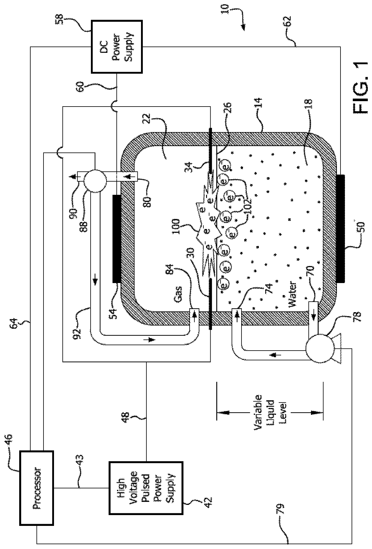
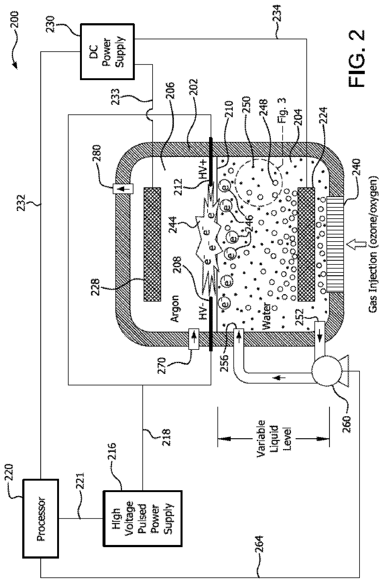
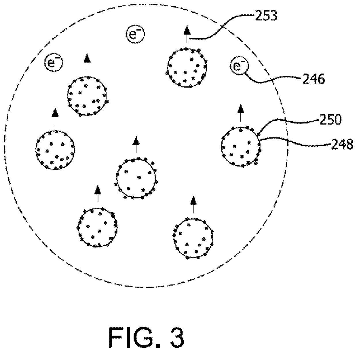
[0019]A reactor system for reacting liquid phase chemical species in a liquid includes a reactor vessel for containing the liquid phase and a gas phase. The reactor vessel can have a gas injection port, a gas exit port, and a liquid-gas interface location within the reactor vessel. A pulsed discharge cathode and anode are provided for creating a pulsed discharge electric field at the liquid-gas interface location. A pulsed discharge power supply delivers a pulsed power input to the pulsed discharge cathode and anode, and thereby creates a plasma comprising ions at the liquid-gas interface location. A secondary electric field source is provided for directing a secondary electric field transverse to the liquid-gas interface. The secondary electric field will drive some of the ions from the gas phase into the liquid phase to react with the liquid phase chemical species.

[0020]The ions that are created in the plasma will be a function of the gas that it subjected to the pulsed discharge ...


PUM

PropertyMeasurementUnit
electric fieldaaaaaaaaaa
frequencyaaaaaaaaaa
gap distanceaaaaaaaaaa

Abstract

A reactor system for reacting liquid phase chemical species in a liquid includes a reactor vessel for containing the liquid phase and a gas phase. The reactor vessel can have a gas injection port, a gas exit port, and a liquid-gas interface location within the reactor vessel. A pulsed discharge cathode and anode are provided for creating a pulsed discharge electric field at the liquid-gas interface location. A pulsed discharge power supply delivers a pulsed power input to the pulsed discharge cathode and anode, and thereby creates a plasma comprising ions at the liquid-gas interface location. A secondary electric field source is provided for directing a secondary electric field transverse to the liquid-gas interface. The secondary electric field will drive some of the ions from the gas phase into the liquid phase to react with the liquid phase chemical species. A method for reacting a liquid phase chemical species is also disclosed.

Description

CROSS-REFERENCE TO RELATED APPLICATIONS[0001]This application claims priority to U.S. Provisional Patent Application No. 62 / 738,358 filed Sep. 28, 2018, entitled Gas / Liquid Plasma Reactor With Pulsed Power Supply and Secondary Direct Current Electrodes,” the entirety of which is incorporated herein by reference.STATEMENT REGARDING FEDERALLY SPONSORED RESEARCH AND DEVELOPMENT[0002]This invention was made with government support under Contract No. CBET1702166 awarded by the National Science Foundation. The government has certain rights in this invention.FIELD OF THE INVENTION[0003]The present invention relates generally to plasma reactors, and more particularly to plasma reactors for reacting liquid, gas, and / or liquid-gas interfacial chemical species.BACKGROUND OF THE INVENTION[0004]Per- and poly-fluoroalkyl substances (PFAS) are a group of approximately 5,000 human-derived chemicals that are used in consumer products such as cookware, food packaging, and carpets, and in industrial a...

Claims


Application Information

Patent Timeline
Patent Type & Authority Patents(United States)
IPC IPC(8): C02F1/46C02F1/70H05H1/48C02F101/36C02F103/06
CPCC02F1/4608C02F1/70H05H1/48C02F2101/36C02F2103/06C02F2201/46C02F2201/4617C02F2201/46175C02F2201/46135C02F2001/46161C02F1/4676C02F1/4672C02F1/78H05H1/46H05H1/466
Inventor LOCKE, BRUCE R.WANDELL, ROBERT J.TANG, YOUNENG
Owner FLORIDA STATE UNIV RES FOUND INC
Learn More