System and method for forming a cavity in soft tissue and bone

a technology of soft tissue and bone, applied in the field of devices and methods for forming cavities in soft tissue or bone, can solve problems such as unintended damage and catastrophic problems for patients

Active Publication Date: 2021-06-08
DARTMOUTH HITCHCOCK CLINIC
View PDF5 Cites 0 Cited by
  • Summary
  • Abstract
  • Description
  • Claims
  • Application Information

AI Technical Summary

Benefits of technology

[0007]The present invention overcomes the disadvantages of the prior art by providing a system and method forming a cavity in soft tissue and bone using a drill assembly that includes a powered drill for creating a cavity of desired dimensions. The drill can include a drill shaft assembly; and a drill motor assembly including a plurality of sensors and a controller unit providing guidance as to rotational speed, motion and depth. The drill shaft assembly can include a drill shaft with an articulating tip that can pivot in a radial arc from a first position that is oriented to a longitudinal axis that is drawn along the shaft to a second position that can be oriented to a perpendicular axis that is perpendicular to the longitudinal axis, and a position sensor positioned at a place along the drill shaft. The drill motor assembly can include at least one rotational motor that rotationally drives the drill shaft with a rotational spin and at least one linear actuator that provides a back and forth movement of the drill shaft. The drill motor assembly can also include at least one torque sensor, at least one rotation sensor, and at least one electrical resistance sensor. The drill motor assembly can include at least one programmable controller unit that includes a plurality of programs that provide a user interface and control the functions and operations of the powered drill arrangement. The drill can include a shroud for the drill shaft that can include a port for insertion of water that can be pressurized by an external pump for irrigation and removal of deconstructed bone and marrow material from the cavity created by a drilling procedure. A computer software package can combine user specifications with sensor data to control activation and displacement of the drill. The drill can include a computer software package that provides a user interface, controls drill shaft rotational speed and / or drilling depth. The computer software package can collect and report the status of at least one of a position sensor, a torque sensor, a rotation sensor or an electrical sensor. The computer software package can include a display that displays status of a drilling procedure and an image from an imaging device that is oriented at a region around a drilling entry point in a bone. The computer software package can be programmable for a set of parameters for a drilling procedure and can guide the operation of the drill during the drilling procedure. An anchoring device assembly for a powered drill for creating a cavity of desired dimensions in a bone, the anchoring device anchored to at least one of a nearby bone or a nearby area on the same bone, and the anchoring device including a multi-directional bearing that is guidable in multiple degrees of freedom. The anchoring device assembly can include a cannula drill guide assembly; a spherical bearing assembly; and a base assembly. The cannula drill guide assembly can include a hollow tube that receives an inserted drill member. The spherical bearing assembly can include a spherical bearing that is constructed with a through hole that is sized to receive and contain the cannula drill guide. The spherical bearing assembly can include an outer ring with a locking set screw that can be mounted in the outer ring and that can lock the spherical bearing in a desired orientation. The base assembly can include a pivot mounting; an X-Y stage; and / or a guide housing. The anchoring device can include a base assembly that can include a pivot mounting that can attach the spherical bearing assembly and cannula drilling guide assembly to a X-Y stage. The X-Y stage can be a calibration device and that can rotate through multiple directions and can position the spherical bearing assembly with an attached power drill. The anchoring device can include a guide housing that can be a mounting interface and can include at least two mounting screw holes. The mounting screw holes can be for retaining screws that secure the anchoring device assembly to at least one vertebra. A method for creating a cavity within a selected vertebra for a percutaneous vertebroplasty procedure using a drill assembly according to an embodiment herein can include preparing the location for mounting the anchoring device assembly by creating holes for receiving mounting screws in at least one anchoring vertebrae adjacent to the selected vertebra; placing the anchoring device assembly onto the at least one adjacent anchoring vertebrae and inserting mounting screws through screw holes in a mounting guide and tightening the mounting screws; using a tracking device to orient and position a cannula drill guide assembly towards an intended entry point by determining and implementing the desired x, y and z-axis settings in an X-Y stage; tightening a locking set screw to secure the spherical bearing in place when the cannula drill guide is satisfactorily positioned; mounting a drill assembly onto the anchoring device assembly by inserting a drill shaft assembly into the cannula drill guide until a distal tip of a drill shaft assembly is in proximity to the intended entry point; programming a set of parameters for a cavity creation procedure into a computer software package of a computer device; connecting the drill assembly to a power source, a source of pressurized water; placing an imager so that a field of view of the imager is focused at an entry point and a region surrounding the entry point; establishing communication between the imager and the computer software package; activating the computer software package to conduct a drilling procedure to create a cavity according to a set of pre-programmed parameters; observing and evaluating a progress of a drilling procedure to create a cavity using displayed images from the imager and feedback readings from various related sensors on a display; and removing the drill assembly and anchoring device assembly.

Problems solved by technology

There is a risk of unintended damage due to misalignment of the drill bit and other factors.
Given that the vertebrae are part of the spinal column, inaccuracies in the procedure can lead to catastrophic problems for the patient.

Method used


Image

  • System and method for forming a cavity in soft tissue and bone
  • System and method for forming a cavity in soft tissue and bone
  • System and method for forming a cavity in soft tissue and bone

Examples


Embodiment Construction

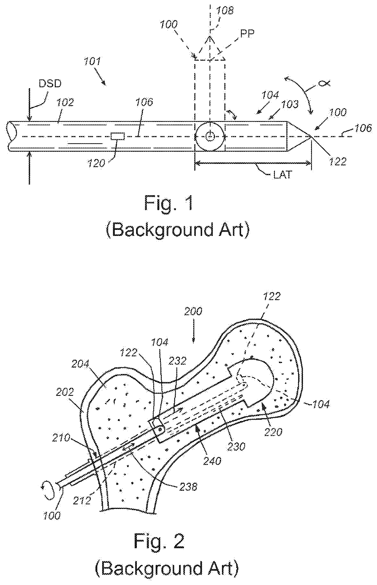
[0015]FIG. 1 is a view of a distal end of a drill, according to the background art. A powered drill can include an electric motor, and a drill shaft assembly 100 that can include a drill shaft 102 that is provided with an articulating tip and a plurality of sensors. A distal end 103 of the drill shaft 102 can include an articulating tip 104 that can have a distal tip 122, as shown in FIG. 1, according to the background art. The articulating tip 104 can be capable of movement describing an angle α of up to 90 degrees from a first position oriented to a longitudinal axis 106 that is drawn along the shaft 102 to a second position oriented to a perpendicular axis 108 that is perpendicular to the longitudinal axis 106. The pivoting motion can be activated by the rotational movement of the drill shaft reaching a threshold speed. As the rotational speed increases, the tip's movement can describe an arc. Above a certain threshold of rotational speed, the tip can move into the perpendicular ...


PUM


Abstract

A system and method for creating a cavity with a drill assembly provides a powered drill shaft assembly having an articulating tip and a position sensor along the drill shaft; a drill motor assembly with a rotational motor, linear actuator, torque sensor, rotation sensor, electrical resistance sensor and a controller unit having a plurality of programs providing user interface and controlling the operation of the powered drill arrangement; a shroud for the drill shaft with a water port; and a computer software package that combines user specifications with sensor data to control activation and displacement of the drill with a user interface, controls the motor for rotational speed and drilling depth, and gives sensor status, and a display displaying status of a drilling procedure and an image from an imaging device, and that is programmable for a set of parameters for a drilling procedure.

Description

RELATED APPLICATIONS[0001]This application claims the benefit of U.S. Provisional Application Ser. No. 62 / 313,651, filed Mar. 25, 2016, entitled SMART CAVITY CREATOR DRILL, the entire disclosure of which is herein incorporated by reference.FIELD OF THE INVENTION[0002]This invention relates to a device and method of forming a cavity in soft tissue or bone in a minimally invasive manner and more particularly, to form an internal cavity having a radius greater than that of the insertion opening.BACKGROUND OF THE INVENTION[0003]Minimizing harm to patients during medical treatment has been a guiding principle of physicians since the days of Hippocrates. For surgeons, this principle has meant minimizing the surgical injury to the patient during procedures while at the same time, achieving the surgical goals. Some practical applications of this principle have achieved new levels of success with the technological advancements of minimally invasive surgery. Techniques using indirect and dire...

Claims


Application Information

Patent Timeline
Patent Type & Authority Patents(United States)
IPC IPC(8): A61B17/00A61B17/16
CPCA61B17/1628A61B17/1626A61B2217/007A61B2562/00A61B17/1617A61B17/17A61B17/1757A61B34/25A61B2034/2051A61B2034/2055A61B2090/066
Inventor MIRZA, SOHAIL K.PAULSEN, KEITH D.HALTER, RYAN J.
Owner DARTMOUTH HITCHCOCK CLINIC
Why Eureka
Try Eureka