Coated tool

a technology of titanium diboride and coating tool, which is applied in the direction of superimposed coating process, chemical vapor deposition coating, milling equipment, etc., can solve the problem of avoiding the large step change in residual stresses in the hard material coating at the boundary to the titanium diboride layer, and achieves the effect of improving the adhesion of the fine-grained titanium diboride layer and the operation of the coated tool

Active Publication Date: 2021-08-31
CERATIZIT AUSTRIA GES
View PDF21 Cites 0 Cited by
  • Summary
  • Abstract
  • Description
  • Claims
  • Application Information

AI Technical Summary

Benefits of technology

[0006]It is an object of the present invention to improve the layer adhesion of a fine-grained tita

Problems solved by technology

In particular, a disadvantageous large step change in the residual stresses in th

Method used


Image

  • Coated tool
  • Coated tool
  • Coated tool

Examples


example

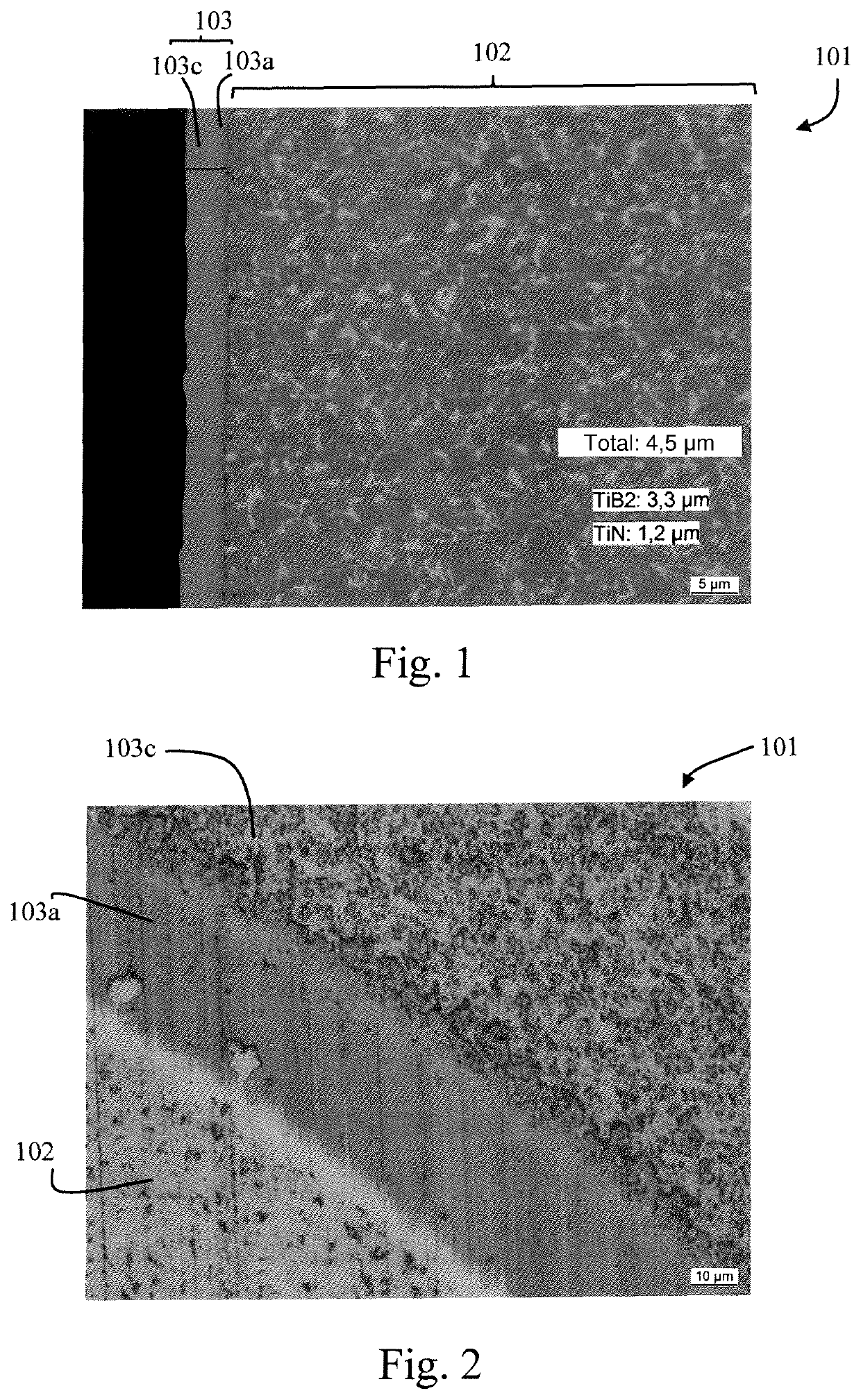
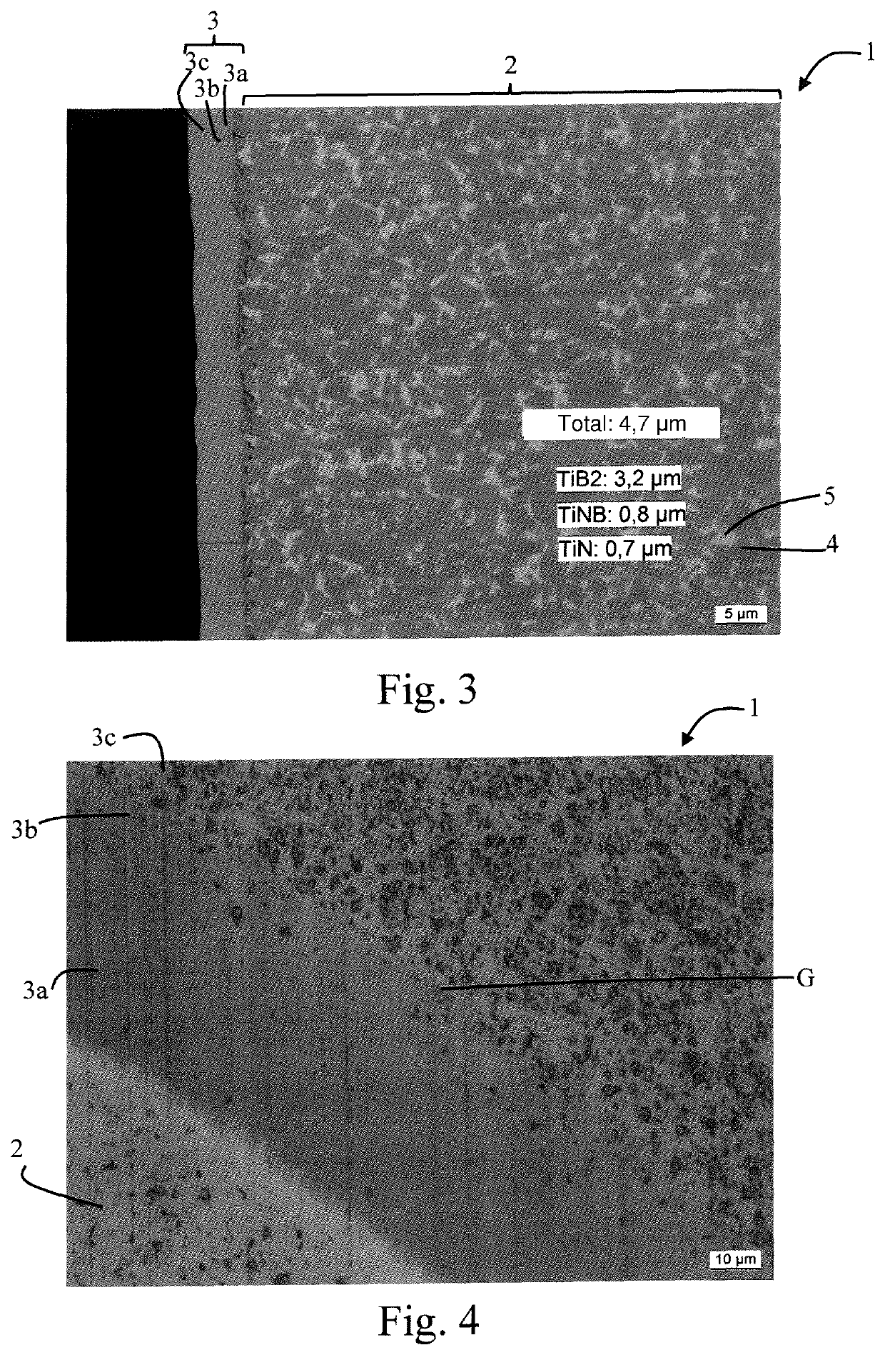
[0044]In order to produce a coated tool 1, an exchangeable cutting insert for the cutting machining of titanium alloys was coated with the hard material coating 3 according to the invention, as described in more detail with the aid of FIG. 3 and FIG. 4. The cutting insert serving as substrate 2 consisted of a commercial cemented hard material produced by the applicant and having a composition of 10% by weight of cobalt, 1.5% by weight of ruthenium, tungsten carbide as balance and an average grain size of the tungsten carbide grains in the range 1.3-2.5 μm.

[0045]A titanium nitride layer 3a having a layer thickness of 0.7 μm was firstly deposited on this substrate 2.

[0046]On top of this titanium nitride layer 3a, an approximately 0.8 μm thick titanium boronitride transition layer 3b having a boron content which increased in steps with increasing distance from the titanium nitride layer 3a was subsequently deposited at about 880° C. The boron content in the titanium boronitride transit...


PUM

PropertyMeasurementUnit
Percent by massaaaaaaaaaa
Thicknessaaaaaaaaaa
Thicknessaaaaaaaaaa

Abstract

A coated tool has a substrate and a hard material coating deposited on the substrate. The hard material coating has a layer structure in the following order, starting from the substrate: a titanium nitride layer, a titanium boron nitride transition layer, and a titanium diboride layer. The titanium boron nitride transition layer has a boron content that increases from the titanium nitride layer in the direction of the titanium diboride layer. The boron content does not exceed 15 at %.

Description

BACKGROUND OF THE INVENTIONField of the Invention[0001]The present invention relates to a coated tool comprising a substrate and a hard material coating which has been deposited on the substrate and comprises, inter alia, a fine-grained titanium diboride layer.[0002]In particular in the cutting machining of metallic materials, not only uncoated tools made of, for example, cemented hard material or cement but also coated tools in the case of which a hard material coating has been deposited on the tool body forming a substrate in order to improve the wear resistance and cutting properties of the tool further have been used for many years. The tool can, for example, be formed in one piece from the substrate material with a shaft for connection to a cutting machine, for example as a solid cemented hard material tool, but it can, in particular, also preferably be configured as an exchangeable cutting insert which can be fastened in an exchangeable manner to a tool main element.[0003]Ceme...

Claims


Application Information

Patent Timeline
IPC IPC(8): C23C28/04C23C28/00C23C16/34C23C16/38B23C5/00C22C29/08
CPCC23C28/34C23C16/342C23C16/38C23C28/044C23C28/44B23C5/006C22C29/08C23C16/34C23C16/029C23C28/04C23C28/042C23C28/048C23C30/005
Inventor CZETTL, CHRISTOPHTHURNER, JOSEFLECHLEITNER, MARKUSJAEGER, CHRISTIAN
Owner CERATIZIT AUSTRIA GES
Why Eureka
Try Eureka