Apparatus for treating exhaust gas of thermal plant

Active Publication Date: 2021-09-21
EMKO
View PDF22 Cites 0 Cited by
  • Summary
  • Abstract
  • Description
  • Claims
  • Application Information

AI Technical Summary

Benefits of technology

[0025]The present invention can treat the exhaust gas of the thermal power plant very effectively and efficiently. In particular, the present invention can exhibit an excellent treatme

Problems solved by technology

However, treatment facilities in the related art do not satisfactorily treat exhaust

Method used


Image

  • Apparatus for treating exhaust gas of thermal plant
  • Apparatus for treating exhaust gas of thermal plant
  • Apparatus for treating exhaust gas of thermal plant

Examples


Example

EXPERIMENTAL EXAMPLE 1

Exhaust Gas Treatment Experiment

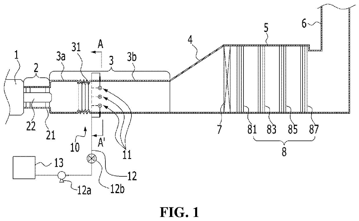
[0084]An apparatus for treating exhaust gas was installed in a reduced model of a combined cycle power plant in a form shown in FIG. 11, and an exhaust gas treatment experiment was performed by injecting a liquid reducing agent (ammonia) in the same molar ratio as nitrogen oxides using injection nozzles. Herein, a catalyst of a catalyst module was a zeolite-based selective catalytic reduction catalyst (a catalyst formed by wash coating Fe-beta zeolite (Zeolyst) on a honeycomb support) was used. A catalyst of a first additional catalyst module was a vanadium-based selective catalytic reduction catalyst mainly composed of V2O5, and a catalyst of a second additional catalyst module was a platinum catalyst which is an oxidation catalyst. Herein, positions of the injection nozzles in a duct are located at positions corresponding to ⅜ of the above-described lineal distance c from a hub, and positions of ends of the injection nozzles ar...

Example

EXPERIMENTAL EXAMPLE 2

Confirmation of Changes in Distribution of Pollutant Treatment Fluid at Rear End of Duct According to Changes in Positions of Injection Nozzles in Duct

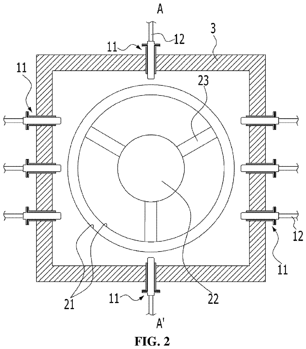
[0088]The following experiment was carried out to confirm changes in mixing distribution of a pollutant treatment fluid according to changes in positions of injection nozzles in a duct. Ammonia water was injected through the injection nozzles inside the duct as shown in FIGS. 1 to 4, and concentration distribution of ammonia was measured in a duct expansion pipe connected to a rear end of the duct. Herein, air which simulates the condition of the fluid discharged from a gas turbine during startup of the gas turbine was injected at the position of the gas turbine. The injection nozzles were arranged on cross section of the duct in a form as shown in FIG. 2, but the experiment was carried out by increasing a spaced distance from a hub along the longitudinal direction of the duct at a constant ratio with respect to ...

Example

EXPERIMENTAL EXAMPLE 3

Confirmation of Changes in Distribution of Pollutant Treatment Fluid at Rear End of Duct According to Changes in Positions of Ends of Injection Nozzles

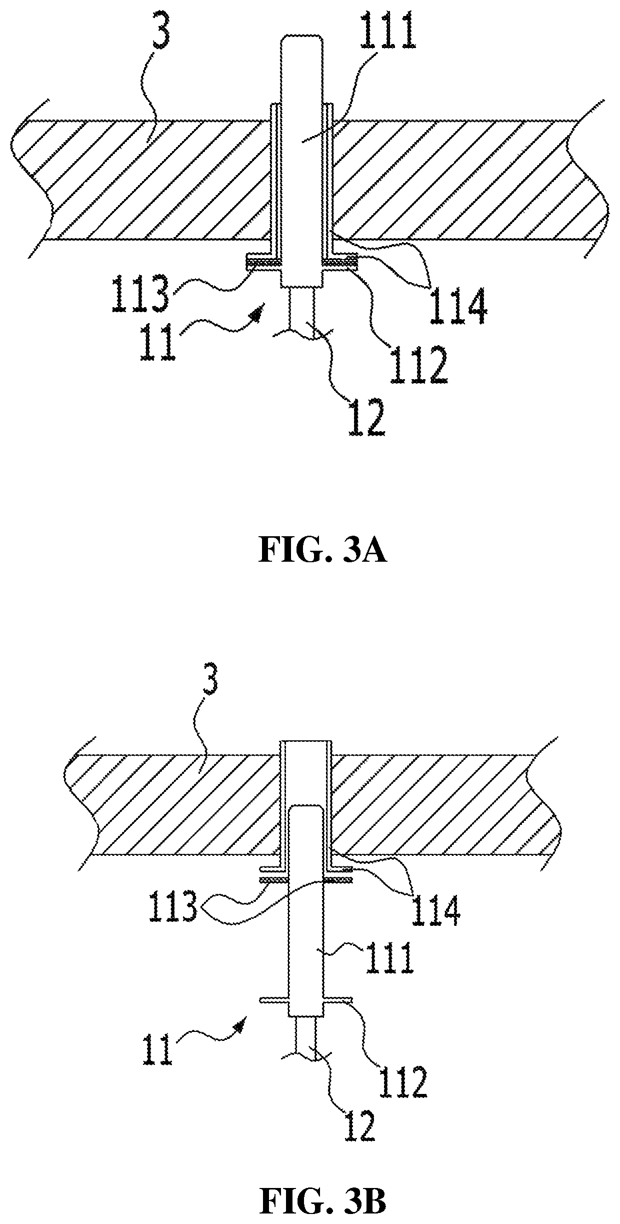
[0091]The following experiment was carried out to confirm changes in distribution of a pollutant treatment fluid according to changes in positions of ends of injection nozzles. In detail, the experiment was carried out by changing several conditions among the conditions of experimental example 2 in such a manner that positions of the injection nozzles in a duct is fixed at ⅜ position with respect to the lineal distance c from a hub and the positions of the ends of the injection nozzles were changed at a constant ratio with respect to the perpendicular line a. Ammonia water injected through the injection nozzles was controlled such that ammonia concentration was 10±1 ppm as a theoretical value in a measuring part, and the other experimental conditions were maintained the same. From this, results as shown in Table ...


PUM

PropertyMeasurementUnit
Fractionaaaaaaaaaa
Fractionaaaaaaaaaa
Fractionaaaaaaaaaa

Abstract

An apparatus for treating exhaust gas of a thermal power plant according to the present invention includes: a diffusion module part controlling an exhaust gas flow between a duct disposed at a rear end of a gas turbine of the thermal power plant and the gas turbine to guide the exhaust gas flow toward an inner wall of the duct; a plurality of injection nozzles installed in a flow section in the duct in which the exhaust gas guided toward the inner wall of the duct from the diffusion module part flows, and protruding from the inner wall of the duct; a fluid supply pipe connected to the injection nozzles and extending outside the duct; a fluid supply part supplying a pollutant treatment fluid in liquid phase to the injection nozzles through the fluid supply pipe; and a catalyst module disposed at rear ends of the injection nozzles.

Description

CROSS REFERENCE TO RELATED APPLICATION[0001]The present application claims priority to Korean Patent Application No. 10-2019-0064906, filed May 31, 2019, the entire contents of which is incorporated herein for all purposes by this reference.BACKGROUND OF THE INVENTIONField of the Invention[0002]The present invention relates generally to an apparatus for treating exhaust gas and, more particularly, to an apparatus for treating exhaust gas of a thermal power plant.Description of the Related Art[0003]Electric power is generally produced in large-scale power plants. In power plants, power generation methods such as thermal power generation generating power by burning fuels, nuclear power generation using nuclear energy, hydroelectric power generation using falling of fluid, and the like are used. In other power generation facilities, power generation methods using solar power, tidal power, wind power, and the like are used.[0004]Of these, thermal power generation, which is a power gener...

Claims


Application Information

Patent Timeline
IPC IPC(8): F01D25/30B01D53/94B01F3/04B01F5/04
CPCF01D25/305B01D53/9431B01F3/04049B01F5/0475B01F5/0486B01D2255/1021B01D2255/20723B01D2255/20738B01D2255/502F05D2220/32B01D53/86B01D2258/018B01D2255/20761B01D2255/50B01D2251/2062B01D2255/904B01D53/8625B01D53/8631F05D2270/08B01F23/2132B01F25/31423B01F25/3143F23J15/04F23J13/02B05B1/02F23J2219/10B01F25/3142
Inventor JO, HAN-JAELEE, SEUNG JAE
Owner EMKO
Why Eureka
Try Eureka