
3-D printable multi-baffled firearm suppressor

a firearm and multi-baffling technology, applied in the field of firearm sound suppressors, can solve the problems of excessive work energy, high decibel noise generation upon firearm discharge, and excessive work energy transmission to the piston during the course of operation, so as to reduce the decibel level of the resultant noise, reduce the kinetic energy and pressure of the propellant gas, and save work energy

Active Publication Date: 2021-09-21
DELTA P DESIGN
View PDF32 Cites 1 Cited by
  • Summary
  • Abstract
  • Description
  • Claims
  • Application Information

AI Technical Summary

Benefits of technology

The patent text discusses firearm suppressors, which are used to reduce the noise and decibel levels caused by firearms. These suppressors work by capturing the high-pressure exhaust gases produced by burning nitrocellulose and directing them towards the projectile to launch it. The suppressor design uses static geometry to induce pressure loss by expanding and contracting, creating a center through-hole for the projectile to pass through. The technical effect of the invention is reduced noise and decibel levels, making firearms more effective and safe.

Problems solved by technology

Moving at supersonic speeds through the bore, the exhaust gases provide the energy to launch the projectile but also result in generation of high-decibel noises upon firearm discharge.
The inventor herein has recognized significant issues, such as the “mirage” effect, related to excess heat build-up that may arise due to the use of a suppressor on a firearm.
As an example, use of a suppressor may result in sustained elevated internal pressures which result in transmission of excess work energy to the piston during the course of operation.
When use of the suppressor results in such a build-up of pressure in the firearm chamber over an extended time (T), the excess work energy may lead to opening of the breech (chamber) sooner than is supported by the original firearm design.
As a second example, use of the suppressor on autoloading firearms may result in excess venting of exhaust gases at the rear of the weapon in the direction of the operator.
Excess venting of exhaust gases at the rear of the weapon is undesirable as the gases may contain toxic substances, and the particulate matter in the gases may foul the weapons chamber.
Furthermore, the successive firing enabled by autoloading weapons may decrease the effective lifetime of the suppressor.
Frequent use of an autoloading weapon with the suppressor may result in a greater requirement for replacement of the suppressor, thereby burdening the operator with increased expense.

Method used


Image

  • 3-D printable multi-baffled firearm suppressor
  • 3-D printable multi-baffled firearm suppressor
  • 3-D printable multi-baffled firearm suppressor

Examples


Embodiment Construction

[0029]An example multi-baffled firearm suppressor is described herein. The following description relates to various embodiments of the sound suppressor as well as methods of manufacturing and using the device. Potential advantages of one or more of the example approaches described herein relate to reducing a time required for the suppressor to return to ambient pressure without adversely impacting performance of the firearm, reducing a mirage effect, improving thermal signature reduction characteristics, improving operating performance with autoloading firearms, reducing the sound signature from the firearm, eliminating rearward venting of exhaust gases during use with semi-automatic weapon, and various other advantages as explained herein.

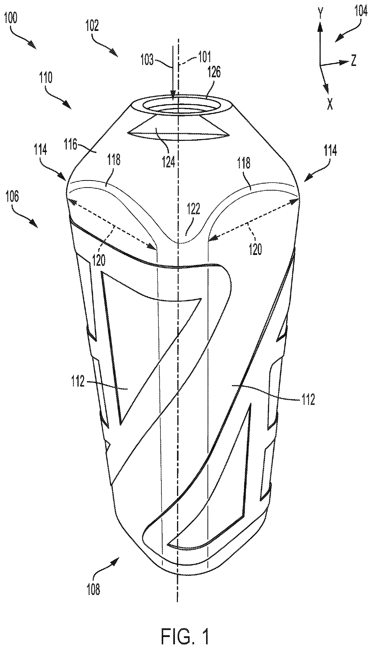
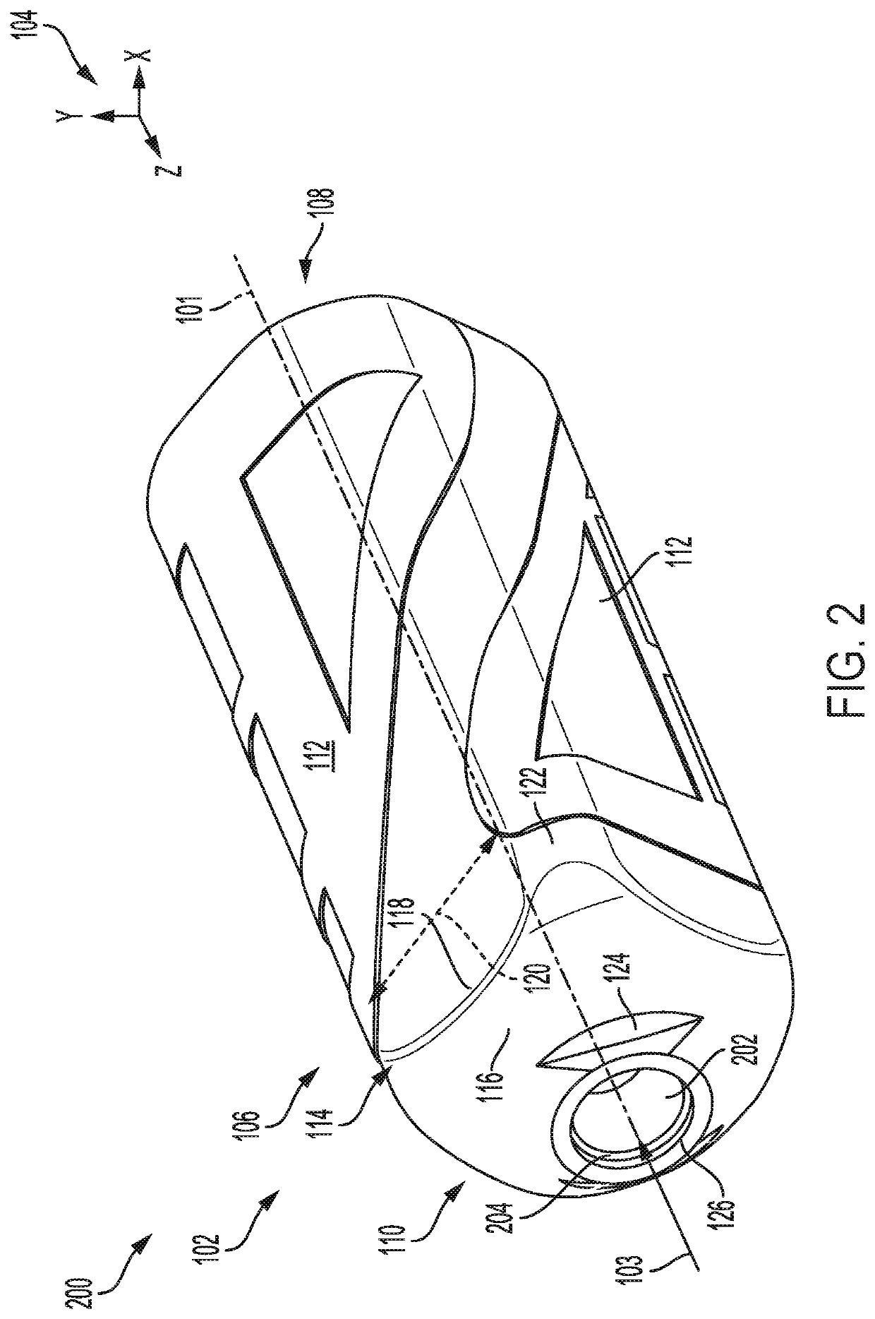
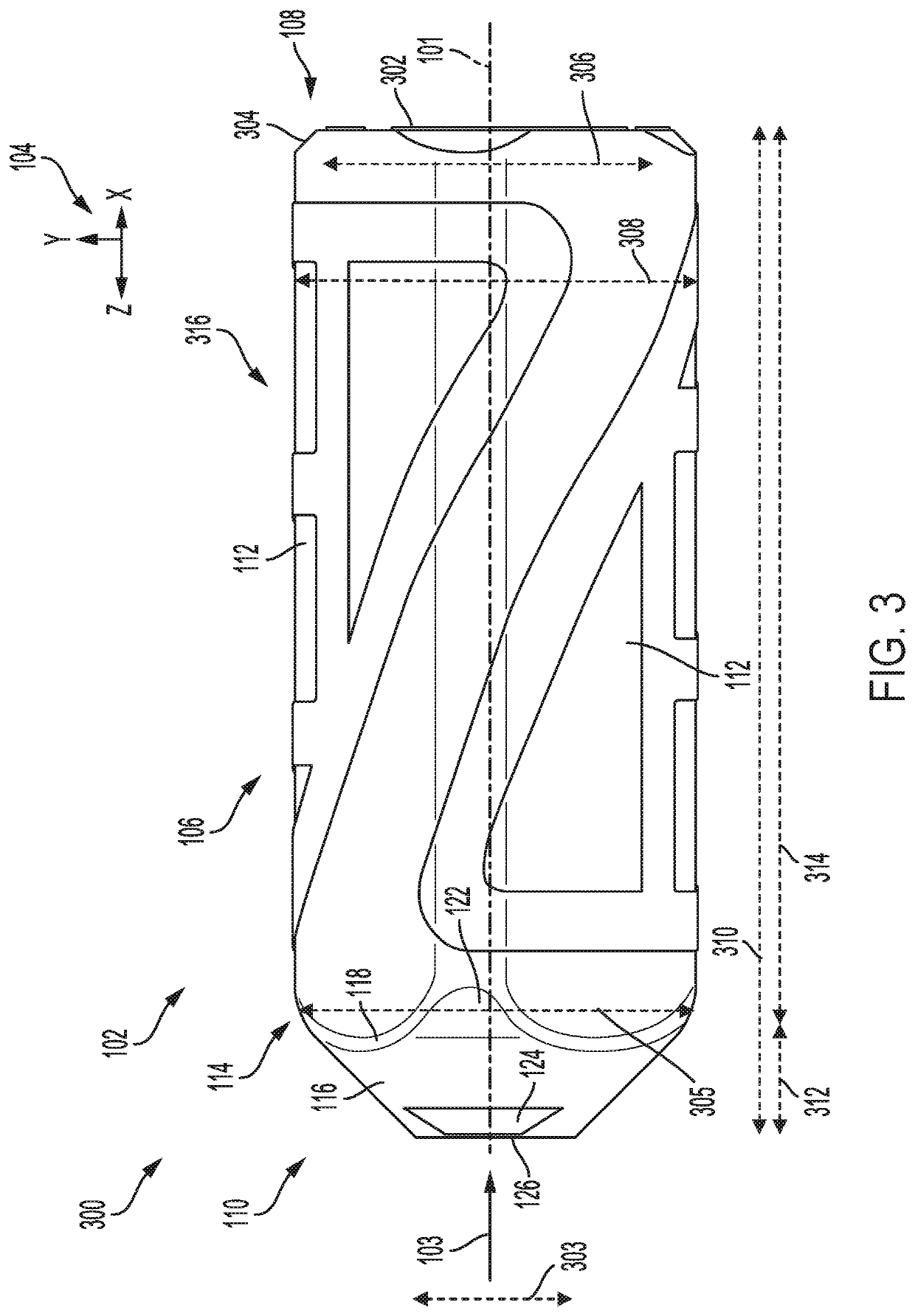
[0030]An exemplary suppressor is shown at FIG. 1, in a first, upright position comprising a sealed continuous outer housing without seams. An isometric view of the suppressor is shown at FIG. 2 from a different perspective than at FIG. 1, depictin...


PUM

PropertyMeasurementUnit
lengthaaaaaaaaaa
diameteraaaaaaaaaa
volumeaaaaaaaaaa

Abstract

Methods and systems are provided for a sound suppressor adapted to be operable with all manners of firearm, including autoloading firearms. In one example, a sound suppressor comprises a unitary single-piece body configured with centrally aligned baffle chambers circumferentially surrounded by exhaust gas chambers.

Description

CROSS REFERENCE TO RELATED APPLICATIONS[0001]The present application claims priority to U.S. Provisional Application No. 62 / 591,672, entitled “3-D PRINTABLE MULTI-BAFFLED FIREARM SUPPRESSOR”, and filed on Nov. 28, 2017. The entire contents of the above-listed application are hereby incorporated by reference for all purposes.FIELD[0002]The present description relates generally to methods and systems for firearm sounds suppressors employing a plurality of baffles.BACKGROUND AND SUMMARY[0003]Firearms utilize high pressure exhaust gases to accelerate a projectile such as a bullet. Firearm silencers (hereafter referred to as “suppressors”) are typically added to the muzzle (exhaust) of a firearm to capture the high pressure exhaust gases of a given firearm. These high pressure exhaust gases are the product of burning nitrocellulose and possess significant energy that is used to accelerate the projectile. The typical exhaust gas pressure of a rifle cartridge in a full length barrel may be...

Claims


Application Information

Patent Timeline
Patent Type & Authority Patents(United States)
IPC IPC(8): F41A21/30
CPCF41A21/30B33Y80/00B22F5/10B22F2999/00Y02P10/25B22F10/28
Inventor PETERSEN, BYRON S.
Owner DELTA P DESIGN
Learn More