Process for lyophilising a product

a technology of lyophilising and product, which is applied in the direction of drying machines, light and heating equipment, bacteria material medical ingredients, etc., can solve the problems of time-consuming cleaning/sterilisation steps, trays must be removed from the freeze dryer, and must be thoroughly cleaned, so as to minimise the risk of product contamination within the bag, the effect of reducing the exposure of the interior of the bag to potential contamination

Active Publication Date: 2021-10-05
4D PHARMA LEON S L U
View PDF46 Cites 3 Cited by
  • Summary
  • Abstract
  • Description
  • Claims
  • Application Information

AI Technical Summary

Benefits of technology

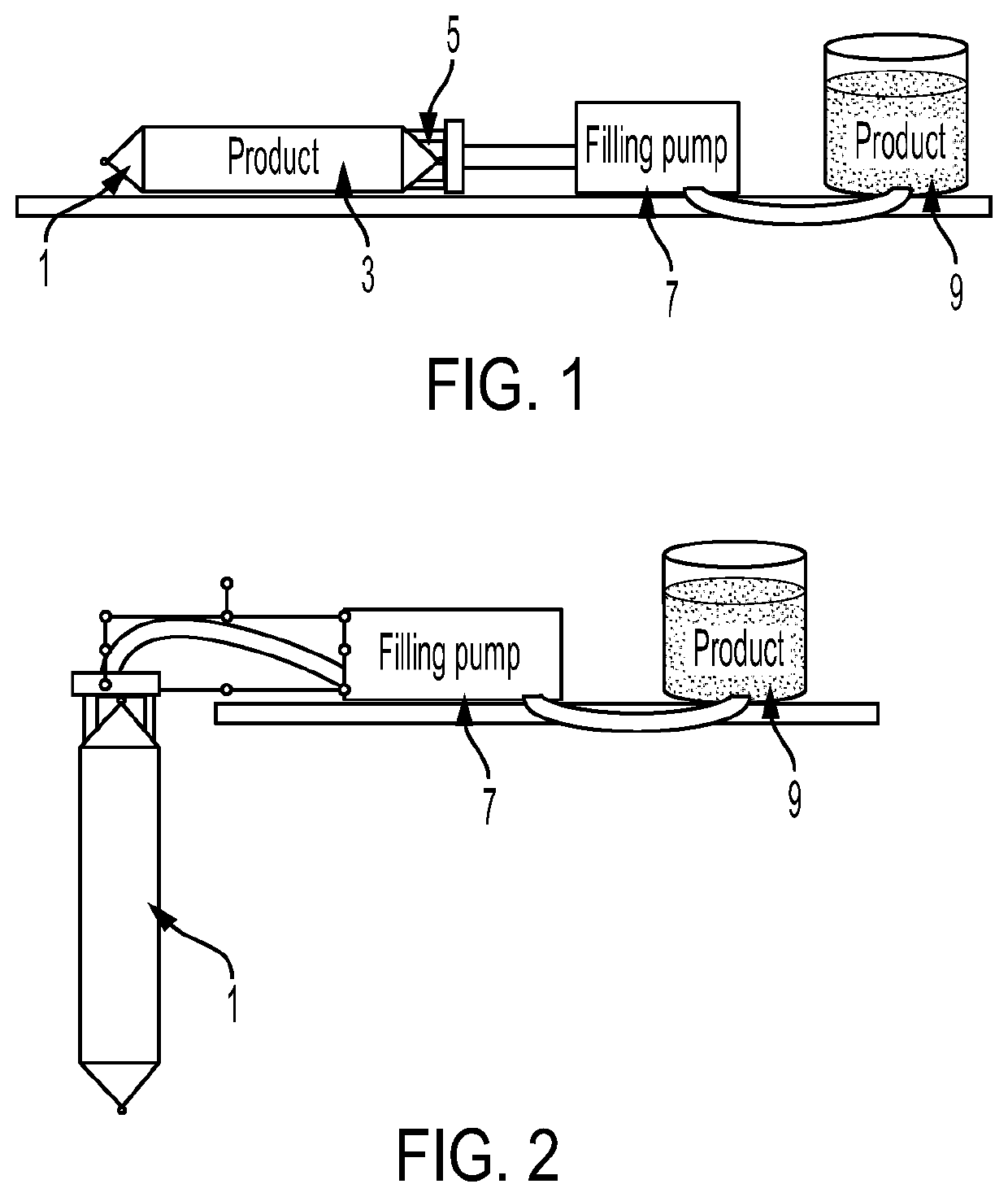
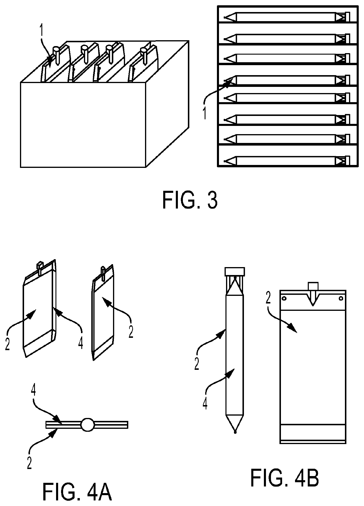
[0046]During the lyophilisation cycle, the bag will typically be placed on a refrigerated shelf which then cools the product in the bag. An even transfer of cooling to the product in the bag is best achieved when the product has a uniform thickness. If the thickness is uneven regions of the material may be cooled (and thus dried) less. To maximise drying of the product within the bag during lyophilisation, the bag may be shaped to evenly distribute the product within the bag such that the thickness or depth of the product within the bag is relatively uniform. This may be achieved through the use of a bag comprising two generally planar panels spaced apart by a side wall, the side wall preferably being of constant height such that, when the bag is filled, the panels are substantially coplanar. The side wall may be provided by lateral gussets in the bag. Configuring the bag in this way is advantageous as it makes it possible to achieve uniform thickness or depth of the product to be lyophilised regardless of the orientation of the bag during filling and loading.
[0075]To minimise the risk of contamination of the product within the bag, the area of the opening made in the wall of the bag may preferably be less than about 50%, less than about 40%, less than about 30%, less than about 20% or less than about 10% of the total area of the exterior of the bag.
[0076]By removing relatively small amounts of wall from the bag, the exposure of the interior of the bag to potential contamination is minimised and is far lower than for open trays used conventionally for lyophilisation.
[0078]Additionally or alternatively, the bag may be provided with particulate barrier means. For example, this could take the form of a moisture permeable membrane (i.e. a membrane having a WVTR of at least about 500, at least about 1000, at least about 1500 or at least about 2000 g·m−2·d−3) or a component comprising such a membrane which closes an opening in the wall of the bag and / or the filling port to prevent the ingress of particulate contaminants into the interior of the bag, while permitting the egress of moisture therefrom.
[0080]While the use of such a membrane can prevent the ingress of particulate contaminants into the interior of the bag, as is demonstrated by the accompanying examples, it has advantageously been found that even without the use of such a barrier, comparable results, in terms of achieved moisture rates and absence of contaminants can be achieved using the process of the invention as compared to using the Lyoguard® tray.

Problems solved by technology

While trays of this type have been used effectively for many years, their use is not appropriate for the preparation of all types of product.
A further disadvantage with conventional steel or plastic freeze dryer trays is that between freeze drying batches of product, the trays must be removed from the freeze dryer, cleaned thoroughly and, in some cases, sterilised.
Such cleaning / sterilisation steps are time-consuming.
Further, there is a risk that imperfect cleaning of the trays between batches could be a further cause of cross-contamination.
Firstly, the water permeable membrane which closes the tray is relatively fragile and prone to damage.
Despite care being taken by the operatives working with the freeze dryer, there is the risk that, through improper stacking, or as a result of other items being placed on top of filled Lyoguard® trays, the water permeable membrane could be pierced or torn.
Additionally, while the moisture permeable membrane permits the egress of moisture from the interior of the Lyoguard® tray, the membrane is not of a ‘one-way’ construction and, thus, re-entry of moisture back into the interior of the tray from the exterior can occur.
Further, especially when the product to be lyophilised is particulate, the membrane can become clogged with the product, minimising its moisture permeability.
Owing to its construction, it has been found that distributing the product to be lyophilised across the interior of the tray evenly can be challenging.
This can lead to non-uniform freezing resulting in pockets of the finished product comprising an unacceptably high moisture content.
Additionally, the capacity of the standard Lyoguard® tray is limited and, in practice, it is challenging to effectively lyophilise quantities of product of greater than 1 kg.
Depending on the product to be lyophilised, a further issue of concern to some users is that, owing to the gas permeability of the upper surface, the interior of the tray cannot be purged or maintained under vacuum, which can be problematic for example if the material to be lyophilised is anaerobic.
A further disadvantage associated with the Lyoguard® tray is its cost.
Owing to its relatively complex structure, presumably, the cost per tray is high.

Method used


Image

  • Process for lyophilising a product
  • Process for lyophilising a product
  • Process for lyophilising a product

Examples


example 2

ce of Processes According to the Present Invention Versus Processes Using Conventional Lyophilisation Apparatus

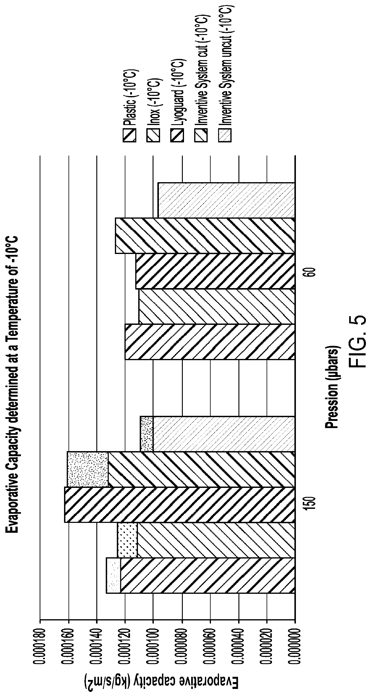
[0103]Tests were conducted to evaluate the freeze drying performance of the process of the present invention as compared to processes using conventionally used apparatus. The bag of Example 1 was tested (both with its filling port opened (shown as “uncut”) and with part of its exterior cut away (shown as “cut”)) alongside a PETG plastic tray, a stainless steel tray (inox) and a Lyoguard tray. The containers were filled with water, frozen and freeze-dried for a defined period at two primary drying temperatures (−10° C. and 0° C.) and two chamber pressures (150 μbars and 60 μbars). The water quantity was measured, which enabled evaporative capacity and the global heat transfer coefficient, Kv, to be determined for each system. The results are shown in FIGS. 5 to 8.

[0104]As can be seen, the performance of the system of the invention was comparable to that of the Lyoguard tray....

example 3

of Bacterial Strains Lyophilised Using the Process of the Present Invention

[0105]Three compositions comprising separate bacterial strains (Roseburia hominis (Strain A), Bifidobacterium breve (Strain B) and Enterococcus gallinarum (Strain C)) as well as sucrose / cysteine lyoprotectants were filled into separate bags as described in Example 1 and then the bags were sealed by closing the filling ports. The contents of the bags were then frozen and the bags loaded into a freeze dryer. As this happened, the end of the bag furthest from the filling port was removed, exposing the interior of the bag, and the cut bag was then subjected to lyophilisation cycles, according to the conditions shown below:

[0106]

Strain AValuesTemperature primary desiccation(PD)−25° C. to −10° C.Vacuum PD150 μbarsTemperature secondary desiccation+25° C.(SD)Vacuum SD50 μbars

[0107]

Strain BValuesTemperature primary desiccation(PD)−30° C. to −10° C.Vacuum PD50 μbarsTemperature secondary desiccation+25° C.(SD)Vacuum SD5...


PUM


Abstract

The present invention relates to a process for lyophilising a product (3), comprising the steps of providing a bulk product (3) loading system in the form of a bag (1), the bag (1) having an interior and an exterior defined by a flexible wall, the bag (1) further comprising a filling port (5) providing access to the interior of the bag (1), filling a product (3) having a first moisture content into the interior of the bag (1) via the filling port (5), and exposing the product (3) in the interior of the bag (1) to a lyophilisation cycle such that the moisture content of the product (3) is reduced from the first moisture content to a second, lower, moisture content.

Description

CROSS-REFERENCE[0001]This application is a continuation of International Application No. PCT / IB2018 / 055246, filed Jul. 16, 2018, which claims the benefit of Great Britain Application No. 1711359.8, filed Jul. 14, 2017, all of which are hereby incorporated by reference in their entirety.FIELD OF THE INVENTION[0002]The present invention relates to processes and apparatus for reducing contamination, such that products can be lyophilised in an efficient and economic manner.BACKGROUND TO THE INVENTION[0003]Lyophilisation is a widely used process for formulating pharmaceutical, biotechnological and other types of product. It is an effective way to prepare solid products, even if those products are pharmaceutical products which are destined to be administered in liquid form to patients. Lyophilisation is also a convenient way to produce preparations containing live organisms, or chemically sensitive products obtained from organisms.[0004]While there are many commercially operated lyophilis...

Claims


Application Information

Patent Timeline
Patent Type & Authority Patents(United States)
IPC IPC(8): A61K9/19A61K9/48A61K35/74F26B5/06F26B5/10F26B25/00F26B25/16
CPCA61K9/19A61K9/48A61K35/74F26B5/06F26B5/10F26B25/002F26B25/16F26B5/044F26B25/063B65D33/00
Inventor CARITE, CHRISTOPHEDECLOMESNIL, SOPHIE
Owner 4D PHARMA LEON S L U
Why Eureka
Try Eureka