Organic electroluminescent element

a technology of electroluminescent elements and organic el elements, which is applied in the direction of organic chemistry, luminescent compositions, semiconductor devices, etc., can solve the problems of extending the life of phosphorescent organic el elements, requiring additional efficiency improvement, and reducing efficiency, so as to achieve stable skeleton, high level of control of charge injection/transport properties, and certain amount of injection and transport properties

Active Publication Date: 2021-11-09
NIPPON STEEL CHEMICAL CO LTD
View PDF15 Cites 0 Cited by
  • Summary
  • Abstract
  • Description
  • Claims
  • Application Information

AI Technical Summary

Benefits of technology

[0020]The application of organic EL elements to display devices, e.g., flat panel displays, and light sources requires that the emission efficiency of the element be improved and that at the same time the stability while being driven is satisfactorily secured. Considering these circumstances, an object of the present invention is to provide a practically useful organic EL element that exhibits a high efficiency while having a low drive voltage, and that exhibits a high stability while being driven.
[0037]The indolocarbazole compounds represented by general formula (1) have a very stable skeleton and, through their isomers and substituents, enable a certain amount of control of the injection and transport properties of the two charges; however, it is difficult using these compounds by themselves to control the amount of injection / transport of the two charges into preferred ranges as referenced above. On the other hand, the biscarbazole compounds represented by general formula (2) enable, based on alterations in the type and number of substituents, a high level of control of the charge injection / transport properties and in addition have the same high skeleton stability as the indolocarbazole compounds. As a consequence, through the use of a mixture of the indolocarbazole compound and this biscarbazole compound, the amount of charge injection into the organic layer can be more precisely regulated than is the case for the individual use of either. In the particular case of use in the light-emitting layer of a delayed fluorescence light-emitting EL element or a phosphorescent light-emitting EL element, a lowest excited triplet energy is exhibited that is high enough to confine the excitation energy produced at the light-emitting layer, and because of this energy outflow from within the light-emitting layer does not occur and a high efficiency at low voltages and a long life can be achieved.

Problems solved by technology

However, extending the life of phosphorescent organic EL elements has been a technical problem.
However, the efficiency is lower than in phosphorescent organic EL elements, and as a consequence additional improvements in efficiency are required.

Method used


Image

  • Organic electroluminescent element
  • Organic electroluminescent element
  • Organic electroluminescent element

Examples


example 1

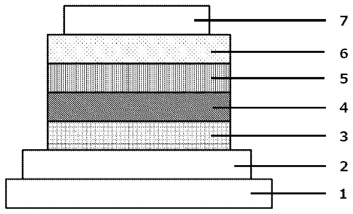
[0110]Each thin film was layered by vacuum vapor deposition at a vacuum of 4.0×10⁻⁵ Pa on a glass substrate on which an ITO anode had been formed in a film thickness of 110 nm. HAT-CN was first formed as a hole injection layer in a thickness of 25 nm on the ITO, followed by the formation of an NPD hole transport layer in a thickness of 30 nm. An HT-1 electron blocking layer was then formed in a thickness of 10 nm. The premix H1 as the host and Ir(ppy)3 as the light-emitting dopant were subsequently co-vapor deposited from different vapor deposition sources to form a light-emitting layer with a thickness of 40 nm. This co-vapor deposition was carried out under vapor deposition conditions that provided an Ir(ppy)3 concentration of 10 wt %. An ET-1 electron transport layer was then formed in a thickness of 20 nm. A 1 nm-thick lithium fluoride (LiF) electron injection layer was formed on the electron transport layer. Finally, a 70 nm-thick aluminum (Al) cathode was formed on the electro...

examples 2 to 9

[0111]Organic EL elements were fabricated proceeding as in Example 1, but respectively using each of the premixes H2 to H9 as the host in Example 1.

example 10

[0112]An organic EL element was fabricated proceeding as in Example 3, except that, after the formation of the light-emitting layer in Example 3, compound 1-11 was formed in a thickness of 10 nm as a hole blocking layer and ET-1 was formed in a thickness of 10 nm as an electron transport layer.


PUM

PropertyMeasurementUnit
weight loss temperaturesaaaaaaaaaa
internal quantum efficiencyaaaaaaaaaa
ionization potentialaaaaaaaaaa

Abstract

Provided is an organic electroluminescent (organic EL) element that exhibits a high efficiency while having a low drive voltage, and that exhibits a high stability while being driven. The organic electroluminescent element contains, in a light-emitting layer formed between an anode and a cathode opposing each other, a first host selected from indolocarbazole compounds represented by general formula (1), a second host selected from carbazole compounds represented by general formula (2), and a light-emitting dopant material. Here, Ar2 and Ar3 are aromatic hydrocarbon groups, L1 is a direct bond or a phenylene group, and L2 is an o-phenylene group.

Description

TECHNICAL FIELD[0001]The present invention relates to an organic electroluminescent element (organic EL element). More particularly, the present invention relates to an organic EL element that contains a first host, a second host, and a light-emitting dopant material.BACKGROUND ART[0002]Upon the application of voltage to an organic EL element, holes are injected into the light-emitting layer from the anode and electrons are injected into the light-emitting layer from the cathode. The injected holes and electrons then recombine in the light-emitting layer to form excitons. Based on statistical rules for electron spin, singlet excitons and triplet excitons are produced at this point at a 1:3 ratio. Fluorescent organic EL elements, which use emission based on singlet excitons, are thus regarded as having a limit of 25% for the internal quantum efficiency. On the other hand, phosphorescent organic EL elements, which use emission based on triplet excitons, are known to have an internal q...

Claims


Application Information

Patent Timeline
Patent Type & Authority Patents(United States)
IPC IPC(8): H01L51/00C09K11/06H01L51/50
CPCH01L51/0067C09K11/06H01L51/001H01L51/0072H01L51/0085C09K2211/1029C09K2211/185H01L51/5012H01L51/5016H01L51/5096H01L2251/5384C07D209/86C07D487/04H10K85/654H10K85/342H10K85/6572H10K50/11H10K2101/10H10K2101/90H10K50/18H10K85/341H10K50/12H10K71/164
Inventor OGAWA, JUNYATADA, MASASHIIKENAGA, YUJI
Owner NIPPON STEEL CHEMICAL CO LTD
Why Eureka
Try Eureka