Fourier transform photoluminescence spectrometer

a photoluminescence and transform technology, applied in the field of spectroscopic instruments, can solve the problems of weak pl signal, difficult to resolve, difficult to optimize the optical path, etc., and achieve the effect of improving the convenience, reliability and weak signal detection capability of pl measurement, and high optical efficiency

Active Publication Date: 2021-12-07
INSA OPTICS TECH SHANGHAI LTD
View PDF1 Cites 0 Cited by
  • Summary
  • Abstract
  • Description
  • Claims
  • Application Information

AI Technical Summary

Benefits of technology

[0020]The flat mirror is used in combination with the dichroic optical filter, the nature of the dichroic optical filter that high transmission in the passband and high reflectivity in the stopband ensures the coexistence and pre-alignment of the optical path with two lasers of different output wavelengths, and warrants on-site selectable laser output without the necessity of adjusting the optical path.
[0032]The present invention has the characteristics of compact with two built-in pump-light lasers, pre-aligned and on-site adjustment-free with high optical efficiency, and turn-key for PL measurement with the sample being placed against the position mark. It eliminates the limitations in the conventional PL measurement that the optical path is hard to optimize while easy to deviate, and the PL signal is weak and difficult to resolve, significantly improves the convenience, reliability and weak signal detection capability of the PL measurement, and hence opens a broad prospects for the applications in the fields of microelectronics, optoelectronics, new materials and physics.

Problems solved by technology

The spectrometer eliminates the limitations in the conventional PL measurement that the PL measurement is very demanding on user's experimental skills, the optical path is hard to optimize while easy to deviate, and the PL signal is weak and difficult to resolve.

Method used


Image

  • Fourier transform photoluminescence spectrometer

Examples


Embodiment Construction

[0035]The present invention will now be described more fully hereinafter with reference to the accompanying drawings, in which exemplary embodiments of the present invention are shown. The present invention may, however, be embodied in many different forms and should not be construed as limited to the embodiments set forth herein. Rather, these embodiments are provided so that this disclosure is thorough and complete, and will fully convey the scope of the invention to those skilled in the art. Like reference numerals refer to like elements throughout.

[0036]In the following, the present invention will be described further in detail with reference to the attached drawings and with particular configuration as example of the 5 functional modules.

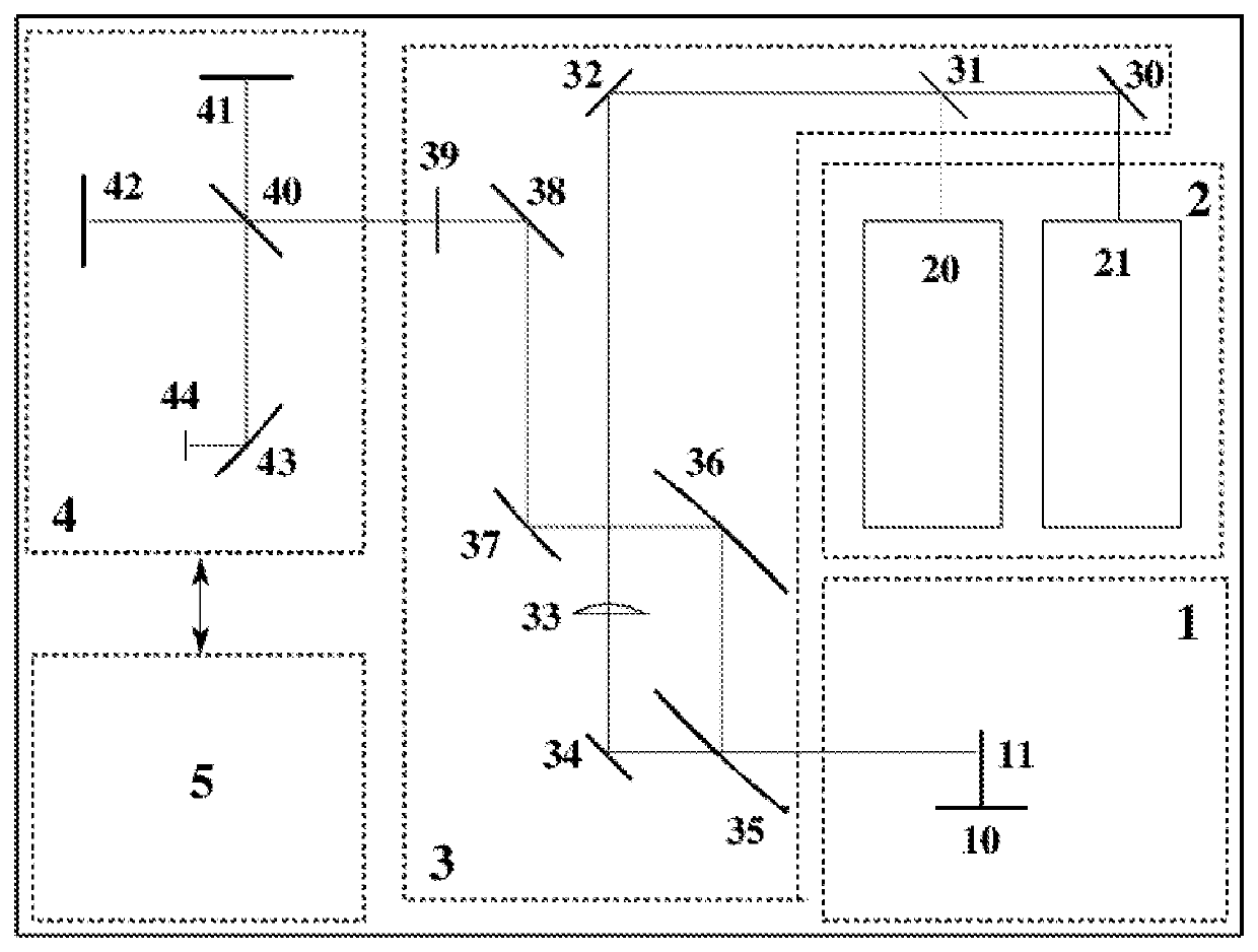
[0037]FIG. 1 is a schematic illustration of the optical configuration of the Fourier transform PL spectrometer and the pre-optimized position for the sample to be tested. As can be seen from the figure, the spectrometer of the present invention...


PUM

PropertyMeasurementUnit
Fourier transform photoluminescenceaaaaaaaaaa
PLaaaaaaaaaa
PL spectroscopyaaaaaaaaaa

Abstract

A compact and miniaturized Fourier transform photoluminescence (PL) spectrometer is provided comprising five functional modules, which are all mounted on a same baseplate: (i) a sample placement module for positioning and spatially adjusting the sample to be tested, which includes a 3-axis stage (10) and a position mark (11) for the expected front surface of the sample being tested. The stage is employed for positioning the sample directly or a low-temperature optical cryostat that contains the sample (said sample and cryostat being not parts of the spectrometer), the position mark indicates the pre-aligned position for the projection of the sample's front surface in the horizontal plane; (ii) a built-in pump light source module for generating PL signal, which includes two lasers (20) and (21) with different laser wavelengths, the lasers' output can be selected on request in the wavelength range from ultraviolet to near-infrared.

Description

CROSS-REFERENCE TO RELATED PATENT APPLICATION[0001]This application claims priority to and the benefit of 201910775040.6, filed Aug. 21, 2019, entitled “Fourier transform photoluminescence spectrometer,” by JIHUA L I et al. The entire disclosure of the above-identified application is incorporated herein by reference.FIELD OF THE INVENTION[0002]The present invention relates to a spectroscopic instrument, and in particular to a Fourier transform photoluminescence (PL) spectrometer for the detection of PL.BACKGROUND OF THE INVENTION[0003]Photoluminescence is as a powerful non-destructive spectroscopy widely used for semiconductor characterization. It can not only reveal the electronic band structures such as band gap and band-tail states of the semiconductor materials, but also provide information on impurities and deep level defects, thereby greatly deepens the understanding of the optoelectronic properties of the materials. Fourier transform spectroscopy is well established in sophis...

Claims


Application Information

Patent Timeline
Patent Type & Authority Patents(United States)
IPC IPC(8): G01N21/64
CPCG01N21/645G01N2021/6471G01N2201/06113G01N21/01G01N21/39G01J3/4535
Inventor LI, JIHUASHAO, JUN
Owner INSA OPTICS TECH SHANGHAI LTD
Why Eureka
Try Eureka