Supercharge Your Innovation With Domain-Expert AI Agents!

Anisotropic iron nitride permanent magnets

a permanent magnet and iron nitride technology, applied in the field of iron nitride magnetic materials, can solve the problems of high price, supply constraints, and impede the ability of individual nanoparticles to rotate, and achieve the effect of reducing the number of permanent magnets

Active Publication Date: 2022-04-19
NIRON MAGNETICS INC
View PDF18 Cites 0 Cited by
  • Summary
  • Abstract
  • Description
  • Claims
  • Application Information

AI Technical Summary

Benefits of technology

The patent describes a new type of magnet made up of aligned iron nitride nanoparticles that have a unique structure called α"-Fe16N2 phase domains. These nanoparticles have a ratio of integrated intensities of an α"-Fe16N2 (004) x-ray diffraction peak to an α"-Fe16N2 (202) x-ray diffraction peak for the aligned iron nitride nanoparticles that is greater than at least 7%, and they also have a squareness measured parallel to the alignment direction that is greater than a squareness measured perpendicular to the alignment direction. The patent also describes the use of these magnets in dispersions and nanocomposites. Finally, the patent describes how the new magnets can be made and used in various forms such as wires, rods, and films. The technical effects of this patent are the creation of a new type of magnet with unique structure and properties that can be used in various applications.

Problems solved by technology

Rare earth permanent magnets are generally encumbered by supply constraints and high prices.
However, electrostatic and electromagnetic forces generally combine to cause nanoparticles to form agglomerates that are typically porous, relatively large clusters of nanoparticles.
These agglomerates may hinder the ability of individual nanoparticles to rotate in response to an external alignment force.

Method used


Image

  • Anisotropic iron nitride permanent magnets
  • Anisotropic iron nitride permanent magnets
  • Anisotropic iron nitride permanent magnets

Examples


examples

[0108]The following examples are put forth so as to provide those of ordinary skill in the art with a complete disclosure and description of how the compounds, compositions, articles, devices and / or methods claimed herein are made and evaluated, and are intended to be purely exemplary and are not intended to limit the disclosure. Efforts have been made to ensure accuracy with respect to numbers (e.g., amounts, temperature, etc.), but some errors and deviations should be accounted for. Unless indicated otherwise, parts are parts by weight, temperature is in ° C. or is at ambient temperature, and pressure is at or near atmospheric. Unless indicated otherwise, percentages referring to composition are in terms of wt %.

[0109]There are numerous variations and combinations of reaction conditions, e.g., component concentrations, desired solvents, solvent mixtures, temperatures, pressures and other reaction ranges and conditions that can be used to optimize the product purity and yield obtai...

example i

-6

[0110]Commercially available nanoparticles of γ-Fe2O3 were obtained as dry, agglomerated powders. The nanoparticle agglomerates were passed through a sieve column and the 25 μm-53 μm size fraction was retained. Seven lots of powder, each lot 2.0 grams in mass, were transformed into iron nitride nanoparticles in a rotary tube furnace. The iron nitride nanoparticles were formed by first by first reducing the nanoparticles into elemental iron Fe by annealing at a temperature of about 340° C. for about 17 hours in hydrogen gas flowing at about 200 standard cubic centimeters per minute (sccm). The Fe nanoparticles were then transformed into iron nitride by annealing at a temperature of about 145° C. for 19 hours in ammonia gas flowing at about 60 sccm. After cooling to room temperature under flowing nitrogen, the iron nitride nanoparticles were passivated by flowing a 1% oxygen / argon mixture over the iron nitride nanoparticles for about 2 hours at a flow rate of about 2 standard cubic ...

example ii

15

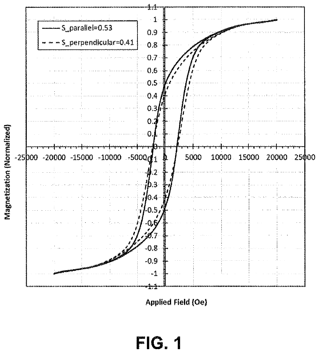
[0120]A second series of passivated iron nitride nanoparticles were prepared, S7 through S15. These passivated iron nitride nanoparticles having a coercivity of 2,521 Oe were sonicated in a 25% oleic acid / methanol solution for about 120 minutes. The ultrasonication was performed with a 200 Watt probe sonicator. The sonicated nanoparticles were washed twice with methanol to remove excess oleic acid. The washed nanoparticles were mixed with epoxy. Table 2 provides the methods by which the samples were prepared prior to magnetic alignment. Each sample was magnetically aligned by placing it between the pole pieces of two permanent magnets. The alignment field was about 5,000 Oe. The samples were allowed to cure overnight. The aligned samples had the shape of a disk and were about 1 mm in thickness and about 6 mm in diameter, with the alignment direction perpendicular to the surface of the disk.

[0121]

TABLE 2Sample preparation methods used for iron nitride nanoparticlesultrasonicated in...


PUM

PropertyMeasurementUnit
weight fractionaaaaaaaaaa

Abstract

Disclosed herein is a permanent magnet comprising: a plurality of aligned iron nitride nanoparticles wherein the iron nitride nanoparticles include α″-Fe16N2 phase domains; wherein a ratio of integrated intensities of an α″-Fe16N2 (004) x-ray diffraction peak to an α″-α″-Fe16N2 (202) x-ray diffraction peak for the aligned iron nitride nanoparticles is greater than at least 7%, wherein the diffraction vector is parallel to alignment direction, and wherein the iron nitride nanoparticles exhibit a squareness measured parallel to the alignment direction that is greater than a squareness measured perpendicular to the alignment direction.

Description

CROSS-REFERENCE TO RELATED APPLICATIONS[0001]This patent application claims priority to U.S. Prov. Appl. No. 62 / 979,668, filed Feb. 21, 2020, and U.S. Prov. Appl. No. 63 / 080,144, filed Sep. 18, 2020. The entire disclosure of each application is incorporated by reference herein for all purposes.FIELD OF THE INVENTION[0002]The disclosed inventions are in the field of iron nitride magnetic materials.BACKGROUND OF THE INVENTION[0003]Permanent magnets can provide high efficiency and reliability for renewable energy technologies. Rare earth permanent magnets are generally encumbered by supply constraints and high prices. Novel magnets formed from more abundant and less strategically important elements are desired to replace rare earth magnets; materials including α″-Fe16N2 are desirable candidates for such “rare-earth-free” magnets.[0004]Permanent nanocomposite magnets may be produced from individual nanoparticles by consolidation. A binder may be used that fixes the nanoparticles in a ma...

Claims


Application Information

Patent Timeline
Patent Type & Authority Patents(United States)
IPC IPC(8): H01F1/047H01F1/06H01F41/02
CPCH01F1/047H01F1/065H01F41/0273H01F1/442H01F1/0045C01P2004/64
Inventor JOHNSON, FRANCISGREGER, RICHARD W.LARSON, JOHN M.WU, YIMINGZHANG, FANDAMIEN, KATHRYN SARA
Owner NIRON MAGNETICS INC
Features
  • R&D
  • Intellectual Property
  • Life Sciences
  • Materials
  • Tech Scout
  • Unparalleled Data Quality
  • Higher Quality Content
  • 60% Fewer Hallucinations
Learn More