Synchronous real time dynamometer and control system

a real-time dynamometer and control system technology, applied in the direction of electrical control, structural/machine measurement, instruments, etc., can solve the problems of limited response time and suitability for relatively modest engine power

Active Publication Date: 2022-04-26
COMBUSTION ORDER LTD
View PDF8 Cites 0 Cited by
  • Summary
  • Abstract
  • Description
  • Claims
  • Application Information

AI Technical Summary

Benefits of technology

[0020]A synchronous dynamometer assembly in accordance with the invention has the advantage that it enables the load applied to the engine to be varied in real time and with sufficient responsiveness that it can be used to control the movement of the piston during the combustion cycle and in particular, during the first 90 degrees after the combustion event in a cylinder so as to enable optimisation of the combustion efficiency. The crankshaft monitoring means enables the application of the load to be synchronised with the engine position and the combustion detection means enables the control means to synchronise the application of the load with the start of combustion.
[0026]The engine crankshaft is preferably hard connected to a generator / alternator, either directly or via power take off (PTO) coupling. The alternator is advantageously a 3 phase alternator, which has the advantage that it will minimise output perturbation. The assembly preferably includes a bridge rectifier for rectifying the 3 phase output of the alternator so a single high voltage load can be employed. The controller is preferably then programmed to use the position of 3 phase voltage peaks in the load calculation.
[0027]In an alternative embodiment the generator is of the switched reluctance type. This has the advantage that the armature does not employ magnets or winding coils and all of the electrical circuits are located on the stator ring. This type of generator is cheap to manufacture and has a wide operating temperature range because the armature is effectively passive and all of the active circuits are located on the stator assembly. This type of generator is capable of operation over a large speed range. The output is in the form of pulses of current as the teeth on the armature pass through the magnetic field generated by the energised stator coils. This type of generator is capable of generating large bursts of current and hence torque on the crankshaft in this application.
[0033]According to another aspect of the present invention, there is provided a method of a controlling the movement of a piston during the combustion cycle of an engine, comprising the steps of connection a synchronous dynamometer assembly according to the invention to the engine so as to enable a variable load to be applied to the crankshaft of the engine, monitoring the rotational position of the crankshaft, monitoring the combustion events in the engine, and varying the load delivered to the non-inductive load of the synchronous dynamometer assembly in real time, in response to the rotational position of the crankshaft and the timing of the combustion event, so as to vary the load applied to the engine at different points during the combustion cycle and thereby control the speed of movement of the piston during the combustion cycle.

Problems solved by technology

The eddy current dynamometer is the most prolific due to its simplicity and low cost, but it is only suitable for relatively modest engine powers due to the difficulty of the cooling the rotating stator.
Even though the load can be electronically controlled the response time is limited due to the requirement to change the current flow through an inductive load (i.e. field coils of an electro-magnet), which is linked to changes in the magnetic field.

Method used


Image

  • Synchronous real time dynamometer and control system
  • Synchronous real time dynamometer and control system
  • Synchronous real time dynamometer and control system

Examples


Embodiment Construction

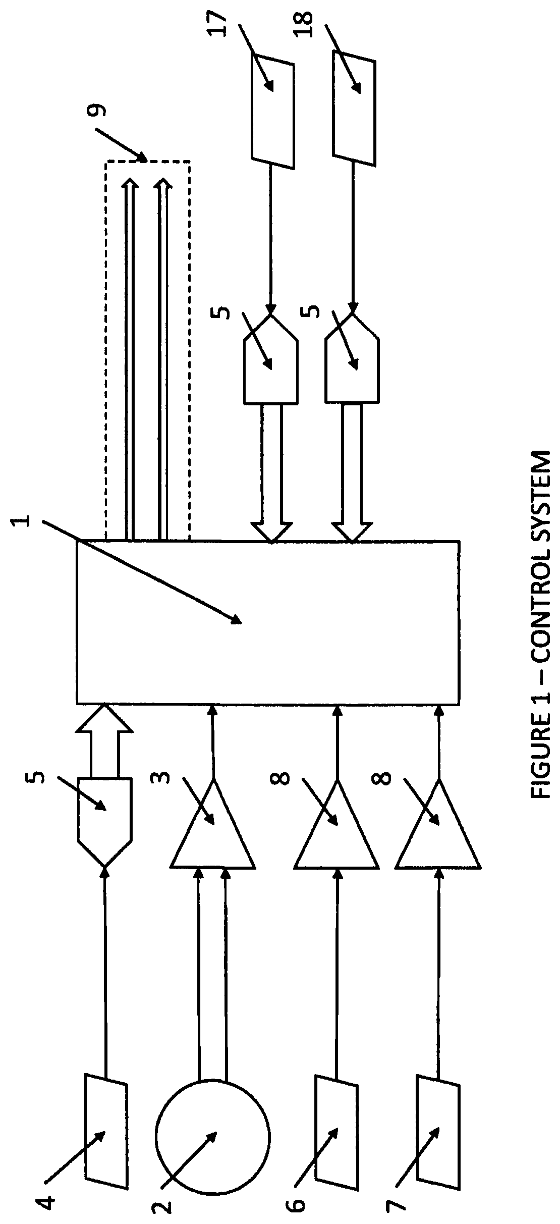
[0054]The present invention provides a dynamometer controlled by an electronic control unit (ECU). The dynamometer ECU can be separate or integrated into the ECU that controls the engine. FIG. 1 shows a crankshaft angle encoder (2) with a differential output which is decoded by a differential receiver (3). The output from the differential receiver is input to the dynamometer ECU (1). The operative inputs to this are;

[0055]Engine crankshaft position

[0056]Detection of the combustion event

[0057]The crankshaft position needs to be determined to a high degree of accuracy. Typically, an angle encoder with better than 1 degree of resolution would be employed, functionally connected to the crankshaft.

[0058]The detection of the combustion event could be achieved by using one, or more of the following;

[0059]Engine cylinder pressure sensor

[0060]Spark ignition (in a gasoline engine)

[0061]Camshaft position sensor (in a four-stroke engine)

[0062]Crankshaft acceleration

[0063]The output of the cylin...


PUM


Abstract

A synchronous dynamometer assembly for applying a load to an engine during at least one portion of the combustion cycle of the engine in a synchronised manner so as to be repeatable each cycle of the engine comprises a dynamometer having a non-inductive load which is applied to the engine during operation to vary the speed of the engine. The non-inductive load is variable by varying the current delivered to it. Crankshaft monitoring means monitors the rotational position of the engine crankshaft, and combustion detection means detects a combustion event in a cylinder of the engine. Control means is operatively connected to the dynamometer for applying the load from the dynamometer to the engine for at least one part of the combustion cycle in real time such that the different loads may be applied to the engine for different parts of the combustion cycle.

Description

BACKGROUND OF THE INVENTION1. Field of the Invention[0001]The present invention relates to dynamometers, and more particularly to dynamometers whose operation is synchronised with the rotational position of an engine to which it is connected, and with combustion events of the engine, and whose load can be applied or changed within several micro-seconds, so as to be sufficiently fast to allow the load to be varied and applied within a combustion cycle.2. The Prior Art[0002]Dynamometers are well known in the field of engine testing. They allow the torque and power output of the engine to be measured under controlled conditions. This is necessary for determining the performance and efficiency of the engine. The dynamometer is used to apply a controlled load to the engine. Controlling the engine power and the dynamometer load independently allows a number of test scenarios to be implemented.[0003]Dynamometers are currently widely used in the automotive sector for engine calibration. Thi...

Claims


Application Information

Patent Timeline
Patent Type & Authority Patents(United States)
IPC IPC(8): F02D41/00F02B63/04F02D29/06F02D33/00G01M15/02G01M15/05G01M15/06G01M15/08
CPCF02D41/009F02B63/042F02D29/06F02D33/00G01M15/02G01M15/05G01M15/06G01M15/08F02D2200/023F02D2200/024G01L3/22G01L1/146G01L3/14
Inventor MARTIN, PETER
Owner COMBUSTION ORDER LTD
Why Eureka
Try Eureka