Joining of ferrous alloy components by fusion welding using a low carbon steel intermediate element

a technology of low carbon steel and ferrous alloy, applied in the field of fusion welding, can solve the problems of increasing the risk of hard and brittle microstructural phases, reducing the weldability of alloys, and difficult fusion welding of parts

Active Publication Date: 2022-06-21
GM GLOBAL TECH OPERATIONS LLC
View PDF1 Cites 0 Cited by
  • Summary
  • Abstract
  • Description
  • Claims
  • Application Information

AI Technical Summary

Benefits of technology

[0005]According to several aspects, a method of joining two ferrous alloy component parts is described. The method includes hot metal casting a portion of a first ferrous alloy component part onto a first joining surface of a low carbon intermediate element; friction fitting, such as press fitting, a joining surface of a second ferrous alloy component part against a sec

Problems solved by technology

However, the carbon content of one of the ferrous alloy parts to be joined may render fusion welding of the parts difficult.
As the carbon content or the carbon equivalency of a ferrous alloy increases, the hardness of the alloy increases and, consequently, the weldability of the alloy decreases due to the formation hard and brittle microstructural phases within the fusion zone and the surrounding heat-affected zone when the molten material created during the prescribed welding operation solidifies rapidly.
These hard and brittle microstructu

Method used


Image

  • Joining of ferrous alloy components by fusion welding using a low carbon steel intermediate element
  • Joining of ferrous alloy components by fusion welding using a low carbon steel intermediate element
  • Joining of ferrous alloy components by fusion welding using a low carbon steel intermediate element

Examples


Embodiment Construction

[0029]The following description is merely exemplary in nature and is not intended to limit the present disclosure, application, or uses. The illustrated embodiments are disclosed with reference to the drawings, wherein like numerals indicate like corresponding parts throughout the several drawings. The figures are not necessarily to scale and some features may be exaggerated or minimized to show details of particular features. The specific structural and functional details disclosed are not intended to be interpreted as limiting, but as a representative basis for teaching one skilled in the art as to how to practice the disclosed concepts.

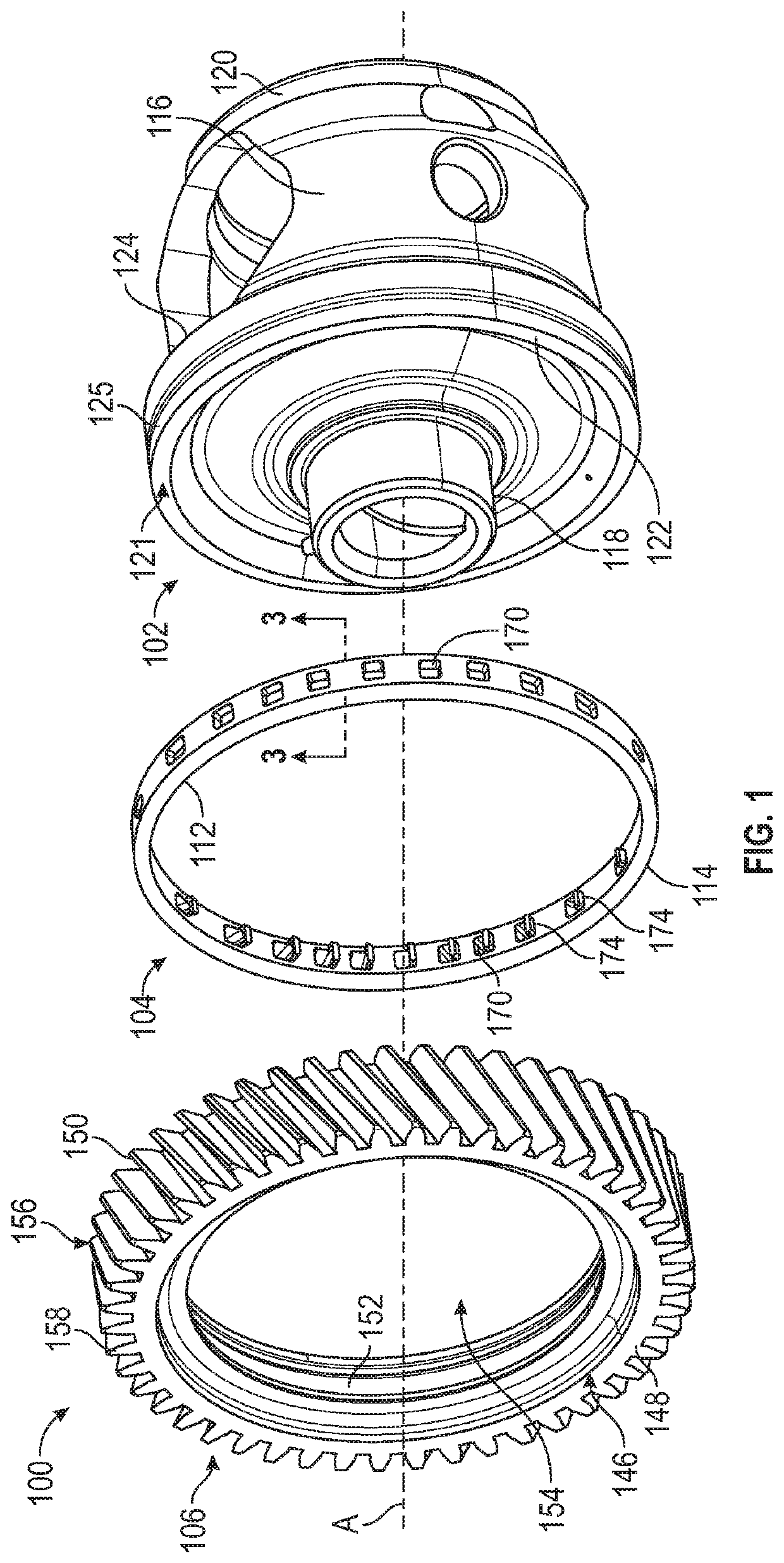
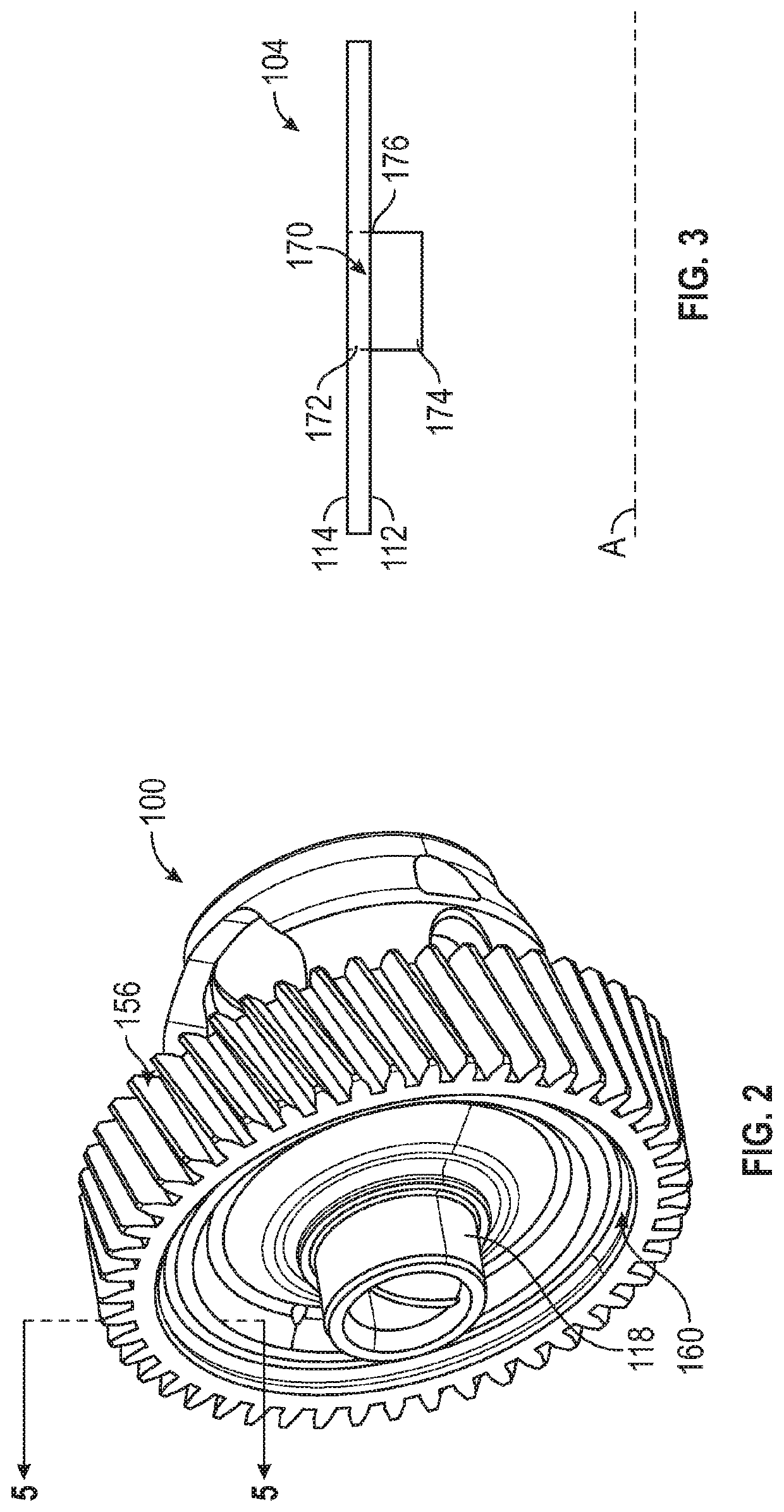
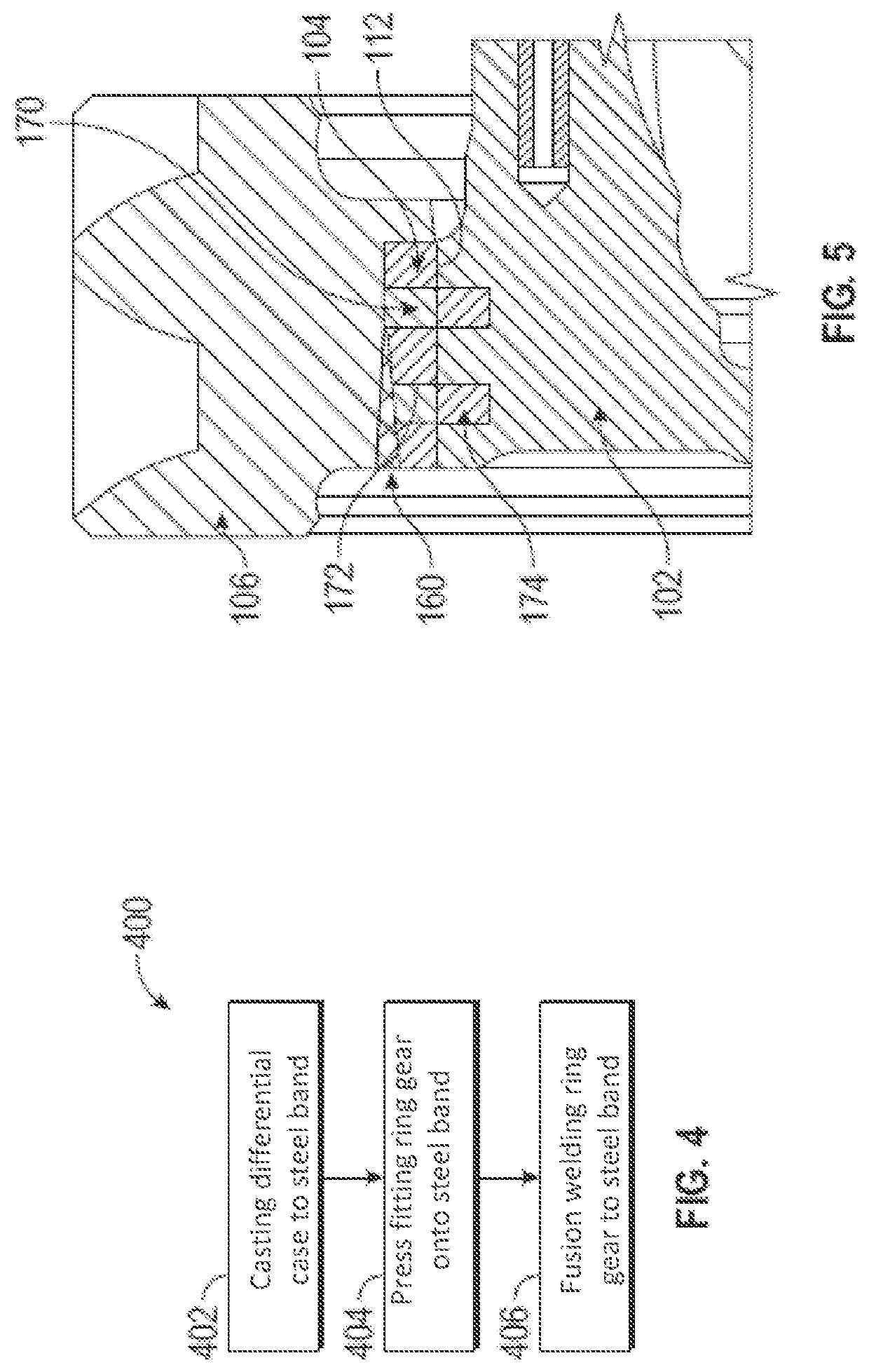
[0030]The present disclosure provides a method of joining a first ferrous alloy component part 102 to a second ferrous alloy component part 106 by fusion welding with a concentrated energy source (e.g., a laser beam, an electron beam, etc.) when at least one of the first and second ferrous alloy component parts 102, 106 is considered unweldable bec...


PUM


Abstract

A method of joining two ferrous alloy component parts. The method includes hot metal casting a portion of a first ferrous alloy component part onto a first joining surface of a low carbon intermediate element; friction fitting a joining surface of a second ferrous alloy component part against a second joining surface of the low carbon intermediate element; and fusion welding with a concentrated energy source the intermediate element to the second ferrous alloy component part. The hot metal casting includes flowing a molten ferrous alloy onto the textured first joining surface, wherein the molten ally encompasses tabs extending from the first joining surface and filling apertures defined in the intermediate element. Then cooling the molten ferrous alloy such that a metallurgical and mechanical bond is formed between the portion of the first ferrous alloy component part and the first joining surface of the low carbon intermediate element.

Description

INTRODUCTION[0001]The present disclosure relates to fusion welding of two or more ferrous alloy component parts, in which one of the component parts has a high carbon content not suitable for fusion welding to the other of the component parts.[0002]The manufacture of certain complex automotive components may require the joining of two or more ferrous alloy component parts. Fusion welding operations, such as laser welding, are prefer methods of joining ferrous alloy component parts. However, the carbon content of one of the ferrous alloy parts to be joined may render fusion welding of the parts difficult. As the carbon content or the carbon equivalency of a ferrous alloy increases, the hardness of the alloy increases and, consequently, the weldability of the alloy decreases due to the formation hard and brittle microstructural phases within the fusion zone and the surrounding heat-affected zone when the molten material created during the prescribed welding operation solidifies rapidl...

Claims


Application Information

Patent Timeline
IPC IPC(8): B23K26/244B23K26/00B23K35/30B22D19/04F16H57/02B22D19/00B23K101/00
CPCB23K26/244B22D19/0036B22D19/04B23K26/0006B23K26/0093B23K35/306F16H57/02B23K2101/008F16H2057/02017B23K26/21B23K26/702C22C37/04C22C37/10C22C37/08B23K26/211B23K26/282B23K26/323B23K2103/02B23K2103/06B23K2103/18B23K26/242F16H48/42F16H2048/382
Inventor LI, HUAXINWANG, LIANGGERARD, DALE A
Owner GM GLOBAL TECH OPERATIONS LLC
Why Eureka
Try Eureka