Clock step control circuit and method thereof

a control circuit and clock step technology, applied in the direction of generating/distributing signals, pulse techniques, instruments, etc., can solve the problems of system shutdown, abnormal operation of the core, system shutdown, etc., and achieve the effect of maintaining computing power

Active Publication Date: 2022-07-05
SHANGHAI BIREN TECH CO LTD
View PDF1 Cites 0 Cited by
  • Summary
  • Abstract
  • Description
  • Claims
  • Application Information

AI Technical Summary

Benefits of technology

[0007]In summary, the clock step control circuit and the method thereof in the disclosure are capable of automatically reducing the clock frequency of the clock signal when an overcurrent event occurs, so as to output a core clock signal with an appropriate clock frequency, and the core can maintain the computing power even when an overcurrent event occurs.

Problems solved by technology

As a demand for the computing power of chips (e.g., high performance computing (HPC) chips or AI accelerator chips) is getting higher and higher, the energy consumption of the high-performance chips is also greatly increasing.
However, when peak performance is required, the operating power of a chip may exceed the peak limit of the system design or the chip design, causing the system shutdown, abnormal operations of the core, or even chip damage.
However, the conventional over current protection (OCP) mechanism only shuts down or resets the system to an idle state, resulting in performance loss and overshoot issues, and this makes the system process more complicated.

Method used


Image

  • Clock step control circuit and method thereof
  • Clock step control circuit and method thereof
  • Clock step control circuit and method thereof

Examples


Embodiment Construction

[0014]The accompanying drawings are included to provide a further understanding of the disclosure, and are incorporated in and constitute a part of this specification. The drawings illustrate embodiments of the disclosure and, together with the description, serve to explain the principles of the disclosure.

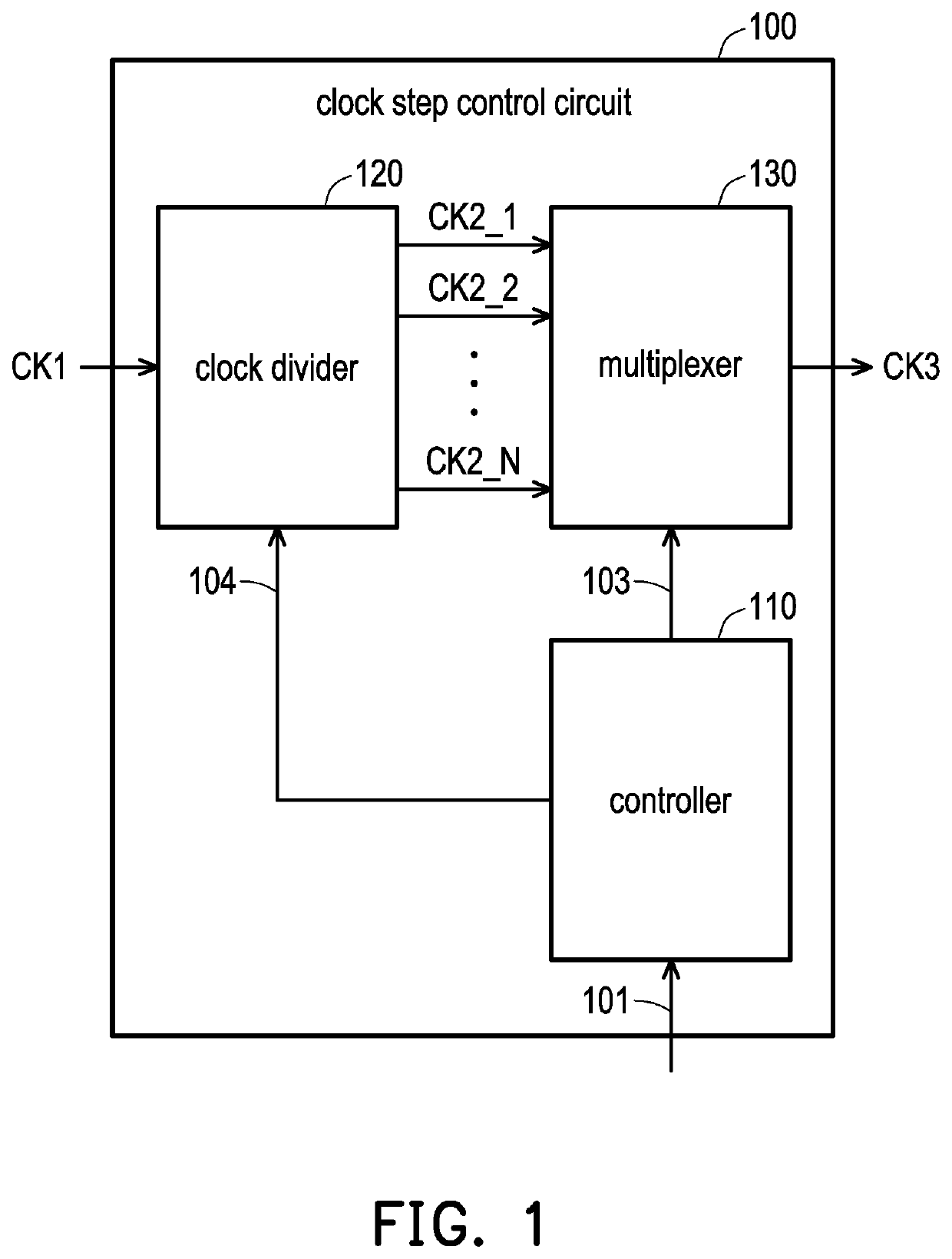
[0015]FIG. 1 is a schematic circuit view of a clock step control circuit according to an embodiment of the disclosure. Referring to FIG. 1, a clock step control (CSC) circuit 100 includes a controller 110, a clock divider 120, and a multiplexer 130. The controller 110 is coupled to the clock divider 120 and the multiplexer 130. The clock divider 120 is coupled to the multiplexer 130. In the embodiment, the clock step control circuit 100 may be disposed in a system-on-a-chip (SoC) and provide a clock signal to the core of the system-on-a-chip (SoC). The system-on-a-chip can be a high performance chip, such as a high performance computing (HPC) chip or an AI accelerator chip, and th...


PUM


Abstract

The disclosure provides a clock step control circuit and a method thereof. The clock step control circuit includes a clock divider, a multiplexer, and a controller. The clock divider receives a first clock signal and outputs multiple second clock signals. The multiplexer receives the second clock signals and outputs one of the second clock signals. The controller is coupled to the clock divider and the multiplexer. When the controller receives an interrupt signal, the controller outputs a selection signal to the multiplexer according to the interrupt signal. The multiplexer outputs another one of the second clock signals according to the selection signal. The clock step control circuit and the method thereof in the disclosure can appropriately switch the clock signal to output a clock signal with an appropriate clock frequency.

Description

CROSS-REFERENCE TO RELATED APPLICATION[0001]This application claims the priority benefit of China application serial no. 202110889954.2, filed on Aug. 4, 2021. The entirety of the above-mentioned patent application is hereby incorporated by reference herein and made a part of this specification.BACKGROUNDTechnology Field[0002]The disclosure relates to a control circuit and a control method, and in particular, to a clock step control circuit and a method thereof.Description of Related Art[0003]As a demand for the computing power of chips (e.g., high performance computing (HPC) chips or AI accelerator chips) is getting higher and higher, the energy consumption of the high-performance chips is also greatly increasing. However, when peak performance is required, the operating power of a chip may exceed the peak limit of the system design or the chip design, causing the system shutdown, abnormal operations of the core, or even chip damage. However, the conventional over current protectio...

Claims


Application Information

Patent Timeline
Patent Type & Authority Patents(United States)
IPC IPC(8): H03K23/60H03K23/00H03K19/08H03K19/173H03K21/10
CPCH03K23/60H03K19/0813H03K19/1737H03K21/10H03K23/002G06F1/08G06F1/12G06F15/7807
Inventor TIAN, ZHENGLIANG, YIKAIZHANG, LINGLANLI, WENQILI, DONGCAIYU, TINGTING
Owner SHANGHAI BIREN TECH CO LTD
Why Eureka
Try Eureka