

Methods for high growth rate deposition for forming different cells on a wafer
a technology of high growth rate and wafer, which is applied in the direction of single crystal growth, polycrystalline material growth, chemistry apparatus and processes, etc., can solve the problems of low quality of 5 m/hr, often has structural defects, and often slow growth of high quality group iii/v materials
- Summary
- Abstract
- Description
- Claims
- Application Information
AI Technical Summary
Benefits of technology
Problems solved by technology
Method used
Image

Examples
example 1
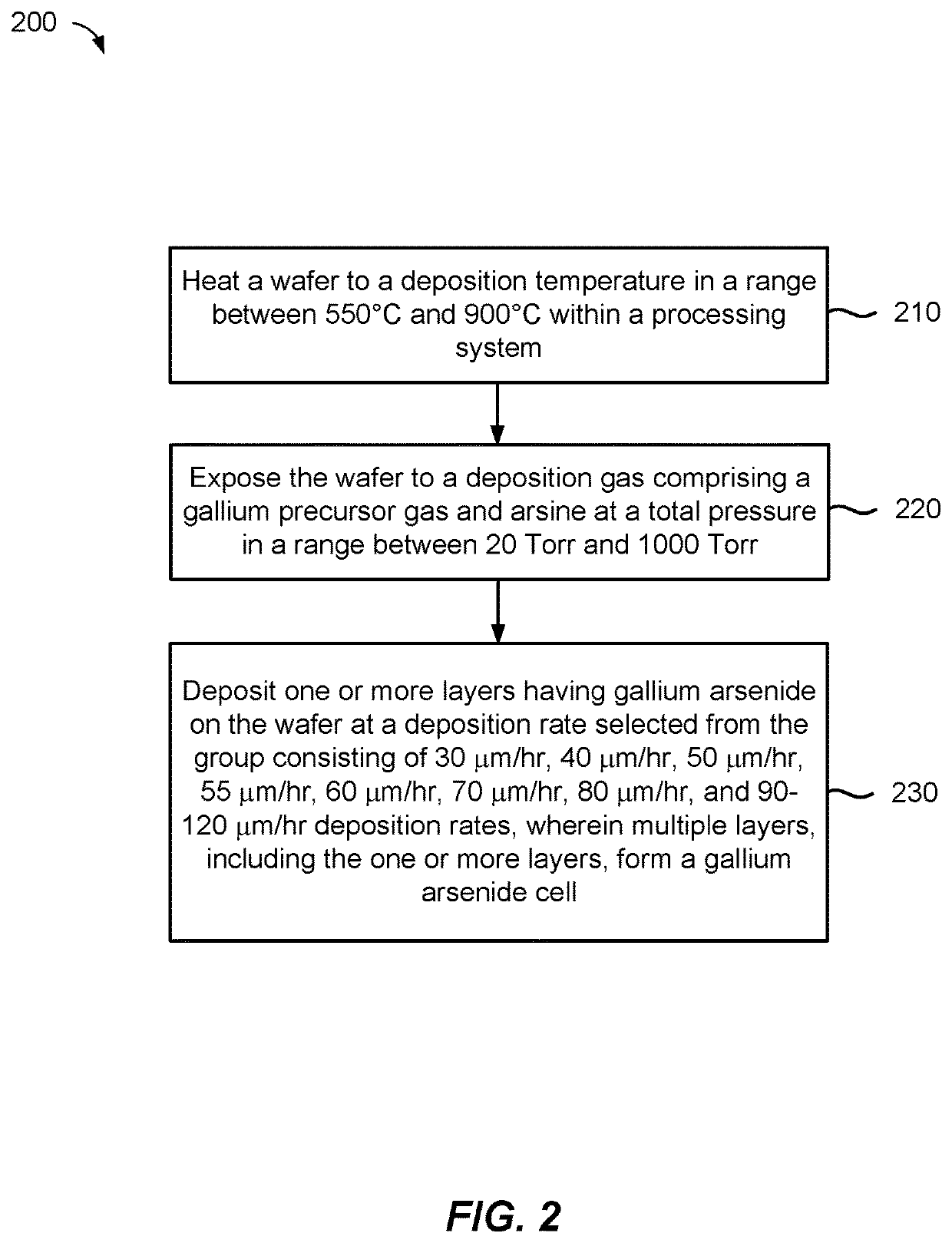
[0043]In one example, the deposition gas may be formed by combining a gallium precursor (e.g., TMG) and an arsenic precursor (e.g., arsine). The substrate may be heated to a deposition temperature and exposed to the deposition gas. The deposition temperature can have a wide range. In one example, the deposition temperature may be within a range from about 600° C. to about 800° C., such as from about 650° C. to about 750° C. or from about 650° C. to about 720° C. In one example, the deposition gas may contain about 100 cc of arsine in about 2,000 cc of hydrogen gas (H2) and about 200 cc of a mixture of TMG / H2 (about 10% TMG in H2. The Group III / V material contains gallium and arsenic and may be deposited at a rate of about 30 μm / hr or greater, such as about 40 μm / hr or greater, preferably, about 50 μm / hr or greater, preferably, about 55 μm / hr or greater, and more preferably, about 60 μm / hr or greater. In an example, deposition rates greater than about 60 μm / hr can include deposition ...
example 2
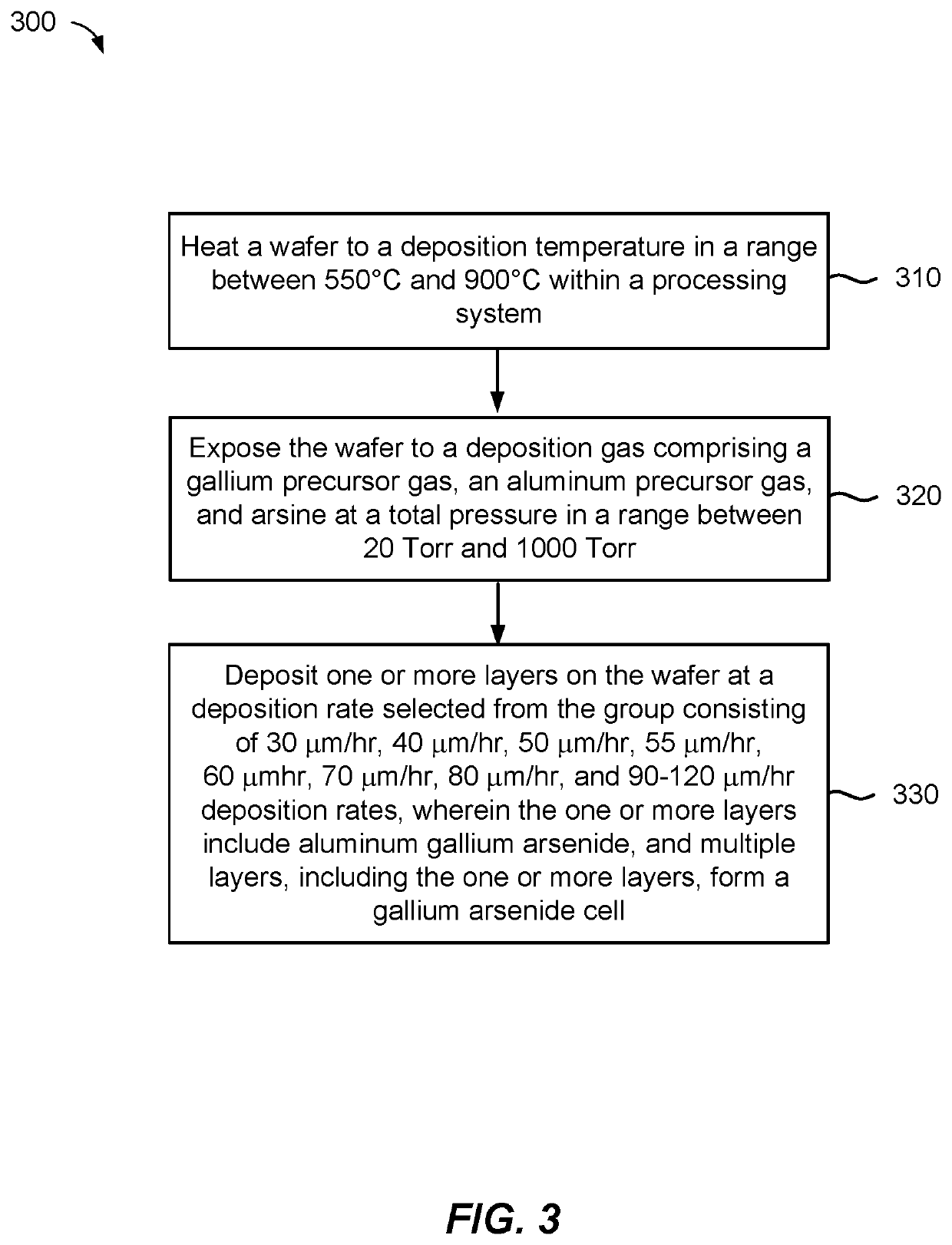
[0044]In another example, the deposition gas may be formed by combining a gallium precursor (e.g., TMG), an aluminum precursor (e.g., TMA), and an arsenic precursor (e.g., arsine). The substrate may be heated to a deposition temperature and exposed to the deposition gas. The deposition temperature can have a wide range. In one example, the deposition temperature may be within a range from about 600° C. to about 800° C. In one example, the deposition gas may contain about 100 cc of arsine in about 2,000 cc of hydrogen gas; about 200 cc of a mixture of TMG / H2 (about 10% TMG in H2); and about 200 cc of TMA / H2 (about 1% TMA in H2). The Group III / V material contains gallium, aluminum, and arsenic and may be deposited at a rate of about 30 μm / hr or greater, such as about 40 μm / hr or greater, preferably, about 50 μm / hr or greater, preferably, about 55 μm / hr or greater, and more preferably, about 60 μm / hr or greater. In an example, deposition rates greater than about 60 μm / hr can include de...
example 3
[0045]In another example, the deposition gas may be formed by combining a gallium precursor (e.g., TMG), an aluminum precursor (e.g., TMA), an indium precursor (e.g., trimethylindium-TMI), and a phosphorus precursor (e.g., phosphine-PH3). The substrate may be heated to a deposition temperature and exposed to the deposition gas. The deposition temperature can have a wide range. In one example, the deposition temperature may be within a range from about 600° C. to about 800° C. In one example, the deposition gas may contain about 200 cc of a mixture of TMG / H2 (about 10% TMG in H2); about 200 cc of TMA / H2 (about 1% TMA in H2); about 200 cc of TMI / H2 (about 1% TMI in H2); and about 100 cc of phosphine in about 2,000 cc of hydrogen gas. The Group III / V material contains gallium, aluminum, indium, and phosphorus and may be deposited at a rate of about 30 μm / hr or greater, such as about 40 μm / hr or greater, preferably, about 50 μm / hr or greater, preferably, about 55 μm / hr or greater, and m...
PUM
 Abstract
Description
Claims
Application Information