Electromagnetic hammer having a moving ferromagnetic mass

a technology of ferromagnetic mass and hammer, which is applied in the direction of drilling machines, percussive tools, bulkheads/piles, etc., can solve the problems of coil damage, lack of rigid support for coils, and compacted coils, so as to reduce the cost and time required, bypass a damaged coil very quickly, and reduce the voltage and hammering rate

Inactive Publication Date: 2001-06-28
ENTREPRISE DE TRAVAUX PUBLICS & PRIVES GEORGES DURMEYER
View PDF0 Cites 13 Cited by
  • Summary
  • Abstract
  • Description
  • Claims
  • Application Information

AI Technical Summary

Benefits of technology

0016] It is then preferable for each junction box to be disposed between two rings of the casing, and to comprise a waterproof housing associated with the inlet and outlet connections of the coil and from which there projects a terminal box receiving elements for connection to the corresponding cables. In particular, the waterproof housing associated with the junction box is filled with a coating material, in particular liquid silicone. The use of such external boxes enables each coil to be tested separately and enables any faults to be identified.
0017] Also preferably, the superposed casings are interconnected by releasable connections, in particular by bolt fastenings, so that each casing is individually interchangeable. In particular, the coils are arranged to enable said hammer to operate in an impaired mode in the event of one of the coils being damaged. Thus, when a fault is detected, the defective coil can be taken electrically out of service by an external modification to the cabling, without that interrupting operation of the hammer which then continues to operate with impaired performance, i.e. with voltages and hammering rates that are reduced. In addition, in the event of a fault in a casing, the external mechanical and electrical accessibility makes it possible for site personnel to swap casings quickly, thereby avoiding the need to take the production tool out of operation for too long.
0018] Because of its modular structure, it is then possible to repair the damaged casing on its own, thereby reducing the cost and the time required for reconditioning.
0019] In a particular embodiment, the n coils are electrically connected in series or in parallel, with the 2n corresponding cables being connected to a connection bar junction box. These connection systems make it possible to bypass a damaged coil very quickly.

Problems solved by technology

That type of hammer presents numerous drawbacks, and the main drawback is the lack of any rigid support for the coil, such that while the mass is being raised, said coil is subjected to a considerable reaction force causing it to become compacted.
In use, these successive deformations of the coil cause the performance of the electromagnetic hammer to diminish and can lead to the coil being damaged.
The problem of the modules withstanding the compression induced by the electromagnetic reaction while the impactor is being raised is not addressed in that document even though that problem constitutes a major weakness for such a device whose modules can deteriorate rapidly.
Nevertheless, winding the coil directly on the tube for the electromagnetic hammer as described above presents certain drawbacks that are explained below.
Using a one-piece internal tube whose length is about 4 meters (m) to 5 m means that it cannot be impregnated with an electrical varnish since the length of such a tube greatly exceeds the capacity of the impregnation baths that are conventionally used.
Consequently, the internal tube of the electromagnetic hammer is relatively vulnerable to moisture, and to mechanical jamming due to the tube swelling.
Furthermore, it has been found that the bottom portion of the coil wound directly on the tube is very highly stressed in use.
Consequently, very high pressure exerted vertical on the windings of the coil run the risk of giving rise to plastic deformation of the coil material (generally copper).
The effect of this deformation is to crush the insulation concerned, which leads progressively to turns becoming short-circuited one to another.
The phenomenon amplifies quickly since the reduction in electrical resistance gives rise to an increase in temperature rise and consequently to the insulation being destroyed by short-circuiting or by overheating.
Finally, it has been found that the above-described electromagnetic hammer structure is relatively vulnerable to moisture due to it being very difficult to make the coil waterproof.
Under such circumstances, if the coil becomes damaged, it is necessary to stop using the electromagnetic hammer and then to remove the coil from the central tube, and that can only be done with equipment that is heavy and bulky, giving rise to the drawback of a prolonged interruption in work.

Method used


Image

  • Electromagnetic hammer having a moving ferromagnetic mass
  • Electromagnetic hammer having a moving ferromagnetic mass
  • Electromagnetic hammer having a moving ferromagnetic mass

Examples


Embodiment Construction

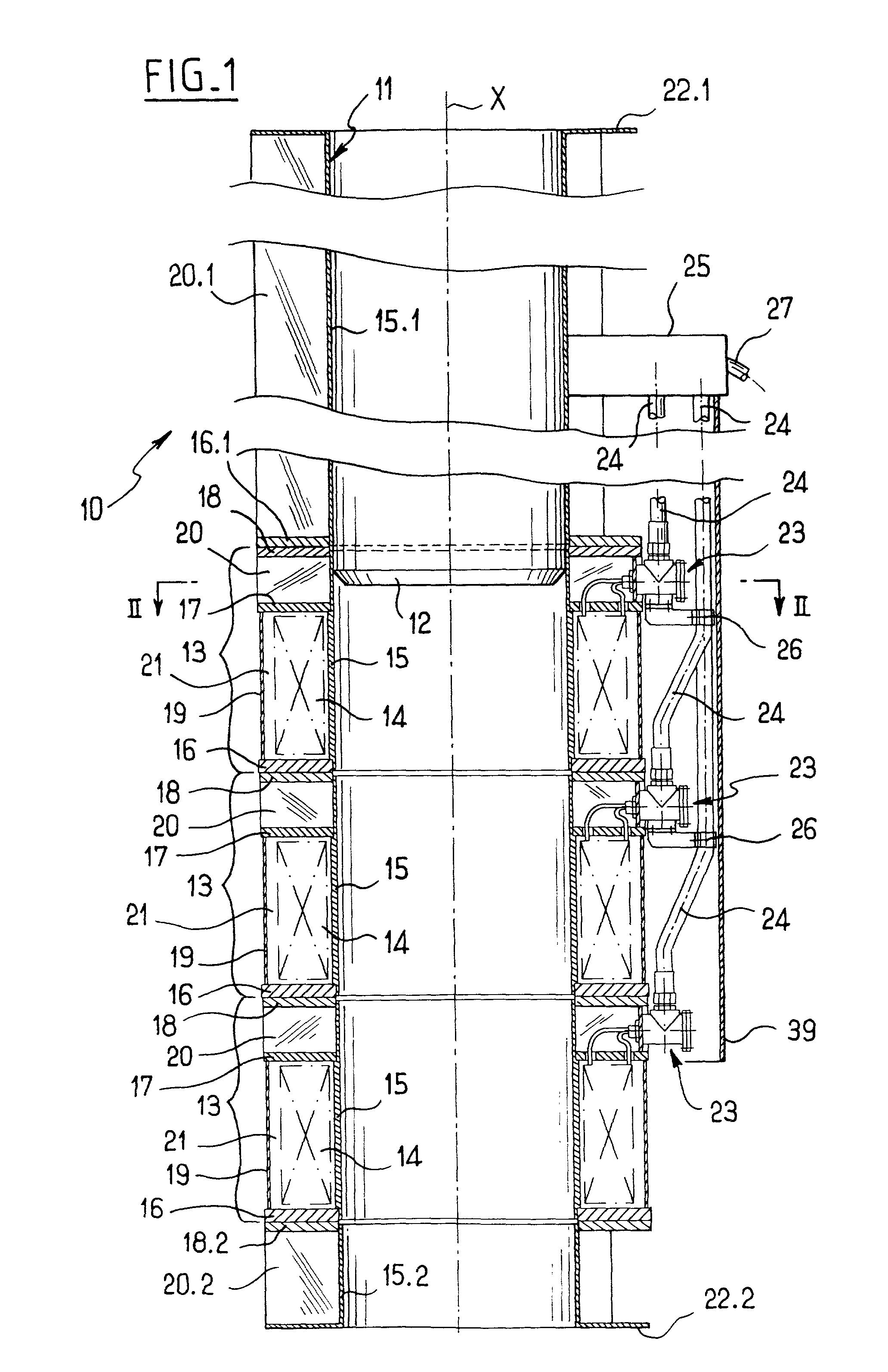
[0026] FIG. 1 shows an electromagnetic hammer 10 of the invention, the hammer being of the type comprising a tube 11 of non-magnetic material for standing on an element engaged in the ground (not shown), said tube being surrounded by a peripheral coil connected to electrical power supply means (not shown here), and slidably receiving a moving ferromagnetic mass referenced 12. The axis of the electromagnetic hammer 10 coincides with the central axis of the tube 11 and is referenced X.

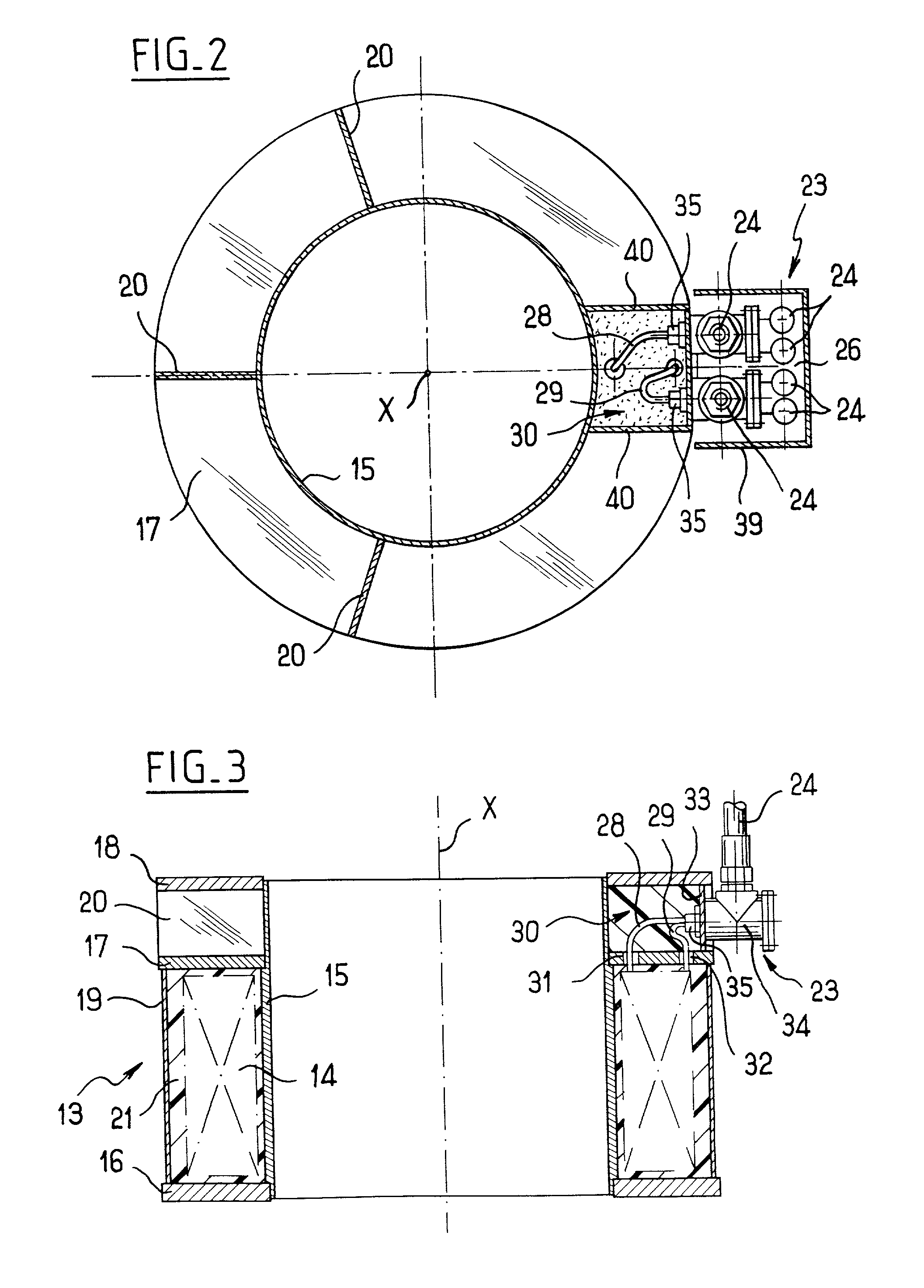
[0027] According to an essential characteristic of the invention, the peripheral coil is subdivided into a plurality (in this case three) independent coils referenced 14, each coil 14 being received in an associated casing 13 and being wound around a cylindrical inside wall 15 of said casing, and the cylindrical walls 15 of the casings 13 are superposed so as to make up the tube in which the moving mass 11 slides.

[0028] Thus, contrary to the single one-piece tube described for the electromagnetic hammer ...


PUM

PropertyMeasurementUnit
lengthaaaaaaaaaa
axial forcesaaaaaaaaaa
massaaaaaaaaaa

Abstract

The invention relates to an electromagnetic hammer having a moving ferromagnetic mass, the hammer being of the type comprising a tube of non-magnetic material for standing on an element that is to be driven into the ground, said tube being surrounded by a peripheral coil connected to electrical power supply means and slidably receiving the moving mass. According to the invention, the peripheral coil is subdivided into a plurality of independent coils, each independent coil being received in an associated casing and being wound around a cylindrical inner wall of said casing, the cylindrical inner walls of the casings being superposed to make up the tube in which the moving mass slides, each casing also having means for taking up axial forces, and a junction box enabling the corresponding coil to be connected to associated electrical power supply cables.

Description

[0001] The present invention relates to an electromagnetic hammer having a moving ferromagnetic mass.[0002] Such hammers are used, for example, on building sites for driving piles in the form of stakes or sheets by percussion, and for doing so in a wide variety of ground types.[0003] A known electromagnetic hammer comprising a tube carrying a coil and having both a moving ferromagnetic mass and an anvil in the vicinity of one of its ends is described in document JP-A-56 153 018, for example. That type of hammer presents numerous drawbacks, and the main drawback is the lack of any rigid support for the coil, such that while the mass is being raised, said coil is subjected to a considerable reaction force causing it to become compacted. In use, these successive deformations of the coil cause the performance of the electromagnetic hammer to diminish and can lead to the coil being damaged.[0004] Document U.S. Pat. No. 5,168,939 discloses a device for drilling an oil well with an electro...

Claims


Application Information

Patent Timeline
Patent Type & Authority Applications(United States)
IPC IPC(8): B25D13/00E02D7/06
CPCE02D7/06
Inventor DURMEYER, GERARDDELPLANCO, MARC
Owner ENTREPRISE DE TRAVAUX PUBLICS & PRIVES GEORGES DURMEYER
Why Eureka
Try Eureka