Nonaqueous electrolyte battery, electrode plate for nonaqueous electrolyte battery, and method for manufacturing electrode plate for nonaqueous electrolyte battery,

a manufacturing method and electrolyte technology, applied in the direction of secondary cells servicing/maintenance, cell components, sustainable manufacturing/processing, etc., can solve the problems of crimping part thickening, unstable impedance of the battery which had the tab plate 10 connected by this method, and method needs an extra work of removing the electrode mix

Inactive Publication Date: 2001-08-09
KK TOSHIBA
View PDF0 Cites 81 Cited by
  • Summary
  • Abstract
  • Description
  • Claims
  • Application Information

AI Technical Summary

Problems solved by technology

But, a battery which had the tab plate 10 connected by this method had an unstable impedance.
And, there were also disadvantages that the crimped part became thick and the tips of crimped part 11 ruptured the separator inducing a short circuit.
But, these methods needed an extra work of removing the electrode mix and wasted the removed electrode mix.
But, since the coating roll is revolving while the backup roll is separated from the coating roll, the coated thickness becomes excessively thick when the backup roll comes in contact again with the coating liquid on the coating roll.
To prevent it from occurring, the coating roll may also be stopped at the same time when the backup roll is separated, but this method is not so effective although some improvement is achieved.
Besides, the coating liquid on the roll is dried unevenly, causing bulges at the start and end of coating.
Thus, the coated layer does not have a uniform thickness, having poor surface smoothness.
But, even if the coating liquid is paused from being supplied by closing the shutter, the coating liquid left on the doctor blade adheres often to the uncoated areas.
Therefore, this method has disadvantages that when a tab plate is connected to the uncoated area by welding, the adhered electrode mix deteriorate a welding strength of the tab plate, and the tab plate is easily separated.
Thus, the method which removes the coated and dried electrode mix layer to expose the base of the conductive base material in order to weld the tab plate needs an extra step and cannot produce the sheet electrode plate efficiently.
The method which forms the electrode mix uncoated areas by means of the shutter disposed immediately before the doctor blade has disadvantages that the electrode mix adhered to the uncoated areas degrades a weld strength of the tab plate and separates the welded tab plate.
Besides, the method of forming the uncoated areas by the roller coating causes bulges at the start and end of coating, possibly cutting the conductive base material while pressing.
And, if the conductive base material is cut off, the opposed rollers are directly contacted mutually, resulting in damaging the roller surfaces.
Thus, batteries using the sheet electrode plates produced by the above methods tend to suffer from deterioration in performance of charging and discharging cycle over a long period.
Specifically, these methods had disadvantages of needing additional processes of changing nozzles and peeling because the supporting material is continuously coated with a predetermined amount of electrode mix.
The sheet electrode plates produced by the above methods are cut to a length suitable for a single cylindrical or square battery and wound into a roll, and when it is particularly used for a cylindrical battery, inflow and outflow of the electrolytic solution owing to the charging and discharging are different between the core and the outer periphery due to a difference in radius of curvature, and performance is easily degraded by a charging and discharging cycle over a long period.

Method used


Image

  • Nonaqueous electrolyte battery, electrode plate for nonaqueous electrolyte battery, and method for manufacturing electrode plate for nonaqueous electrolyte battery,
  • Nonaqueous electrolyte battery, electrode plate for nonaqueous electrolyte battery, and method for manufacturing electrode plate for nonaqueous electrolyte battery,
  • Nonaqueous electrolyte battery, electrode plate for nonaqueous electrolyte battery, and method for manufacturing electrode plate for nonaqueous electrolyte battery,

Examples


embodiment 1

[0128]

[0129] A cathode mix coating liquid having a solid content concentration of 60% by weight was prepared by mixing and dispersing 55.2 parts by weight of LiCoO.sub.2 as the cathode active material, 3.6 parts by weight of acetylene black as the conductive agent, 1.2 parts by weight of a fluororubber based binder as the binding agent, and 40 parts by weight of ethyl acetate as the solvent. This coating liquid had an apparent viscosity of 3000 mPa.multidot.S (a shear rate of 13 sec.sup.-1).

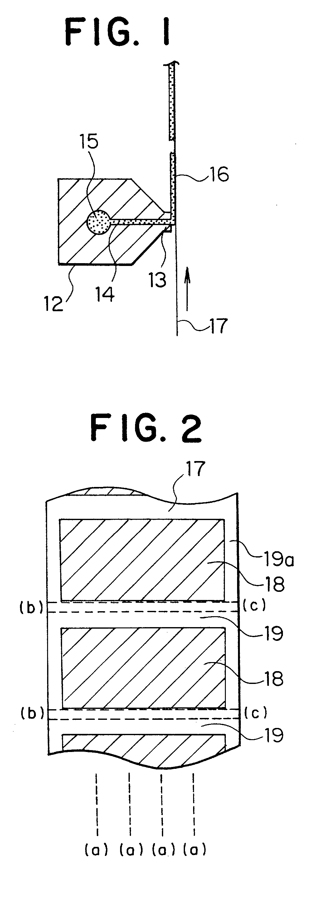
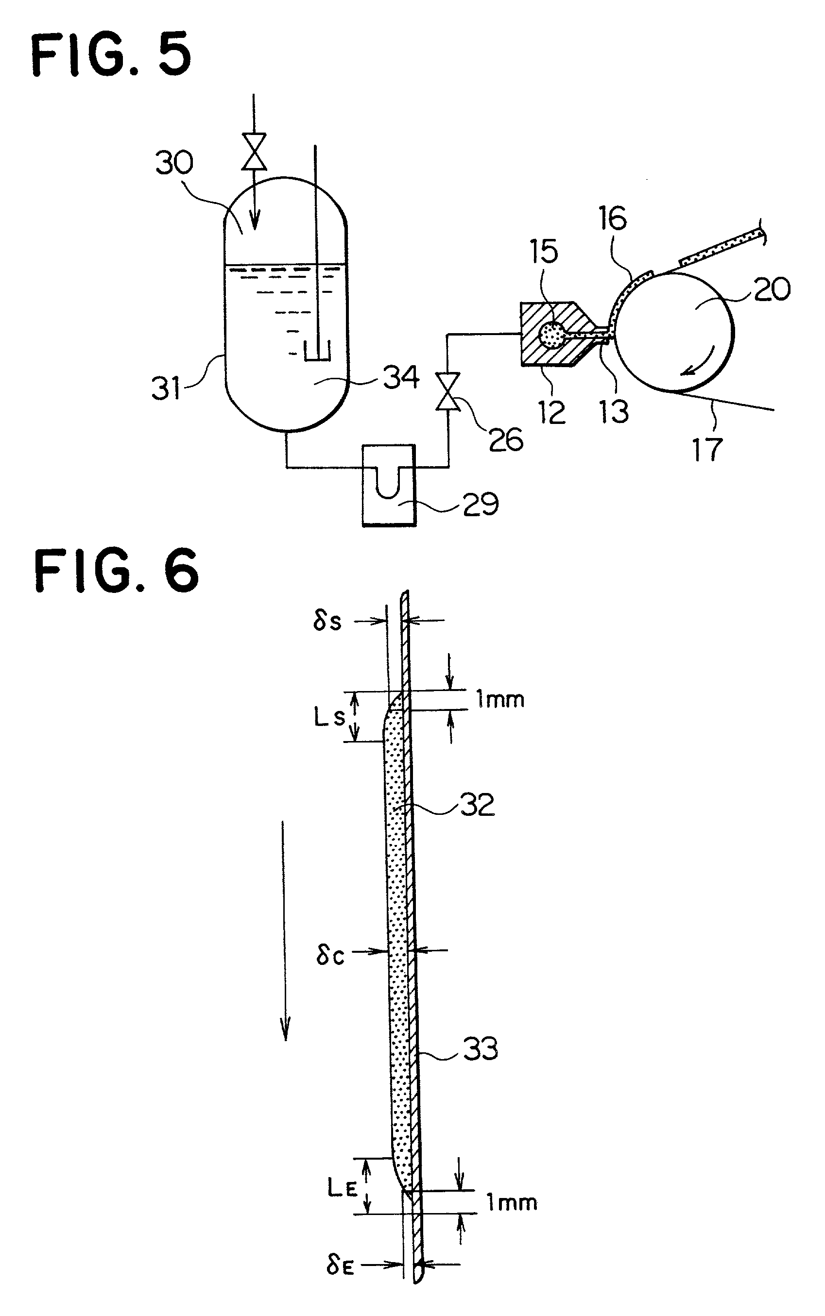
[0130] This slurry-like coating liquid was coated to both surfaces of an aluminum foil having a thickness of 15 .mu.m one surface at a time with uncoated areas formed at predetermined intervals in the longitudinal direction by means of the coating device shown in FIG. 3 according to the method 1) above, and the formed layers were dried in hot air at 120.degree. C. While the coating liquid was being coated, a space between the tips of the lips and the aluminum foil as the conductive base material ...

embodiment 2

[0131]

[0132] A cathode mix coating liquid having a solid content concentration of 65% by weight and an apparent viscosity of 25000 mPa.multidot.S (a shear rate of 13 sec.sup.-1) was prepared by kneading LiCoO.sub.2, acetylene black, a fluororubber-based binder and ethyl acetate in the same way as in Embodiment 1. This coating liquid was coated to both surfaces of an aluminum foil one surface at a time with uncoated areas formed at predetermined intervals in the longitudinal direction in the same way as in Embodiment 1.

embodiment 3

[0133]

[0134] A cathode mix coating liquid having a solid content concentration of 70% by weight and an apparent viscosity of 40000 mPa.multidot.S (a shear rate of 13 sec.sup.-1) was prepared by kneading LiCoO.sub.2, acetylene black, a fluororubber-based binder and ethyl acetate in the same way as in Embodiment 1. This coating liquid was coated to both surfaces of an aluminum foil one surface at a time with uncoated areas formed at predetermined intervals in the longitudinal direction in the same way as in Embodiment 1.


PUM

PropertyMeasurementUnit
thicknessaaaaaaaaaa
thicknessaaaaaaaaaa
thicknessaaaaaaaaaa

Abstract

A method for manufacturing an electrode plate of a nonaqueous electrolyte battery comprises the steps of: running a sheet conductive base material in a first direction; and injecting an electrode material composition containing an electrolyte from a die nozzle onto a first surface of the running sheet conductive base material to form uncoated areas at predetermined intervals on the first surface along the first direction.

Description

[0001] 1. Field of the Invention[0002] The invention relates to a nonaqueous electrolyte battery, an electrode plate for the nonaqueous electrolyte battery, a method for manufacturing the electrode plate for the nonaqueous electrolyte battery, and an apparatus for manufacturing the electrode plate for the nonaqueous electrolyte battery.[0003] 2. Description of the Related Art[0004] A nonaqueous electrolyte battery having lithium as an anode active material is attracting attention as a high-energy density battery, and particularly a primary battery having manganese dioxide, carbon fluoride or thionyl chloride as a cathode active material is extensively used as power supply for a calculator or a timepiece and as a backup battery for a memory.[0005] Besides, with miniaturization and weight reduction of a camcorder, a laptop computer, a portable phone and other various electronic equipment in these years, demands for a secondary battery with a high-energy density as a power supply for s...

Claims


Application Information

Patent Timeline
Patent Type & Authority Applications(United States)
IPC IPC(8): B05C5/02H01M6/10H01M10/052H01M10/0587H01M10/36H01M10/42
CPCH01M4/04H01M4/0402H01M4/0404H01M4/0416H01M4/0419H01M4/0435H01M4/139H01M6/10H01M10/05H01M10/052H01M10/0587Y02E60/122Y10T29/53135Y10T29/49115H01M4/13H01M10/0468Y02E60/10Y02P70/50
Inventor KAIDO, HIDEKIMATSUMOTO, KOUICHIHASHIMOTO, MINORUFURUICHI, MITSURU
Owner KK TOSHIBA
Why Eureka
Try Eureka