
Electric heating element and method for its production

a technology of heating element and heating element, which is applied in the direction of heating arrangement of hot plates, combustion types, lighting and heating apparatus, etc., can solve the problems of heating element ruggedness and volume,

Inactive Publication Date: 2001-09-06
E G O ELEKTRO GERAETEBAU GMBH
View PDF0 Cites 29 Cited by
  • Summary
  • Abstract
  • Description
  • Claims
  • Application Information

AI Technical Summary

Benefits of technology

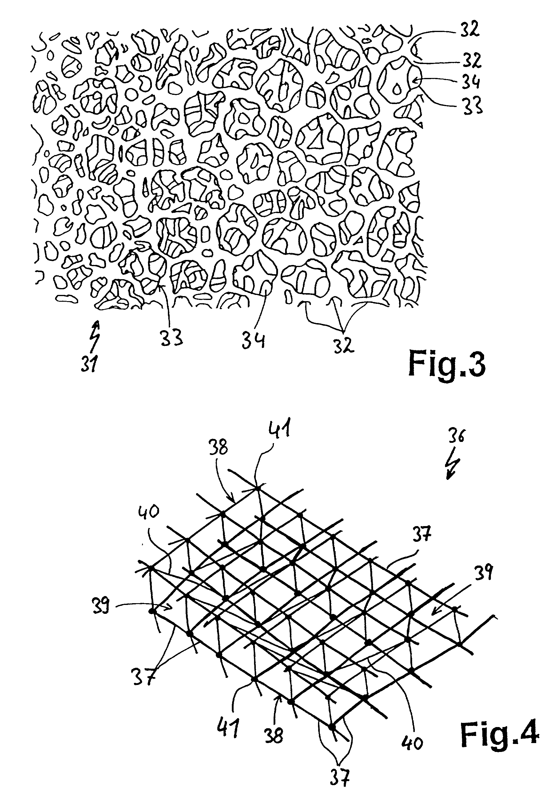
[0008] A further advantageous aspect is the possibility of providing the ceramic material structured and limbed in the form of branchings which may result in, for example, a skeletonized structure in which the branching members are thin as compared to the cavitations. Advantageously the heat conducting material may be configured three-dimensionally meshed, more particularly similar to a three-dimensional textile material.
[0010] It is of advantage when in the course of the elongation of the heating element its electrically effective cross-section remains substantially the same to thus avoid in bent heating conductors the so-called hot paths of increased current flow, especially at the inner side of a curve. This is achieved to particular advantage by the skeletonized structure as described above, the limbs of which approach each other at such inner sides without changing their length or electrically effective conductor cross-section in each case.

Problems solved by technology

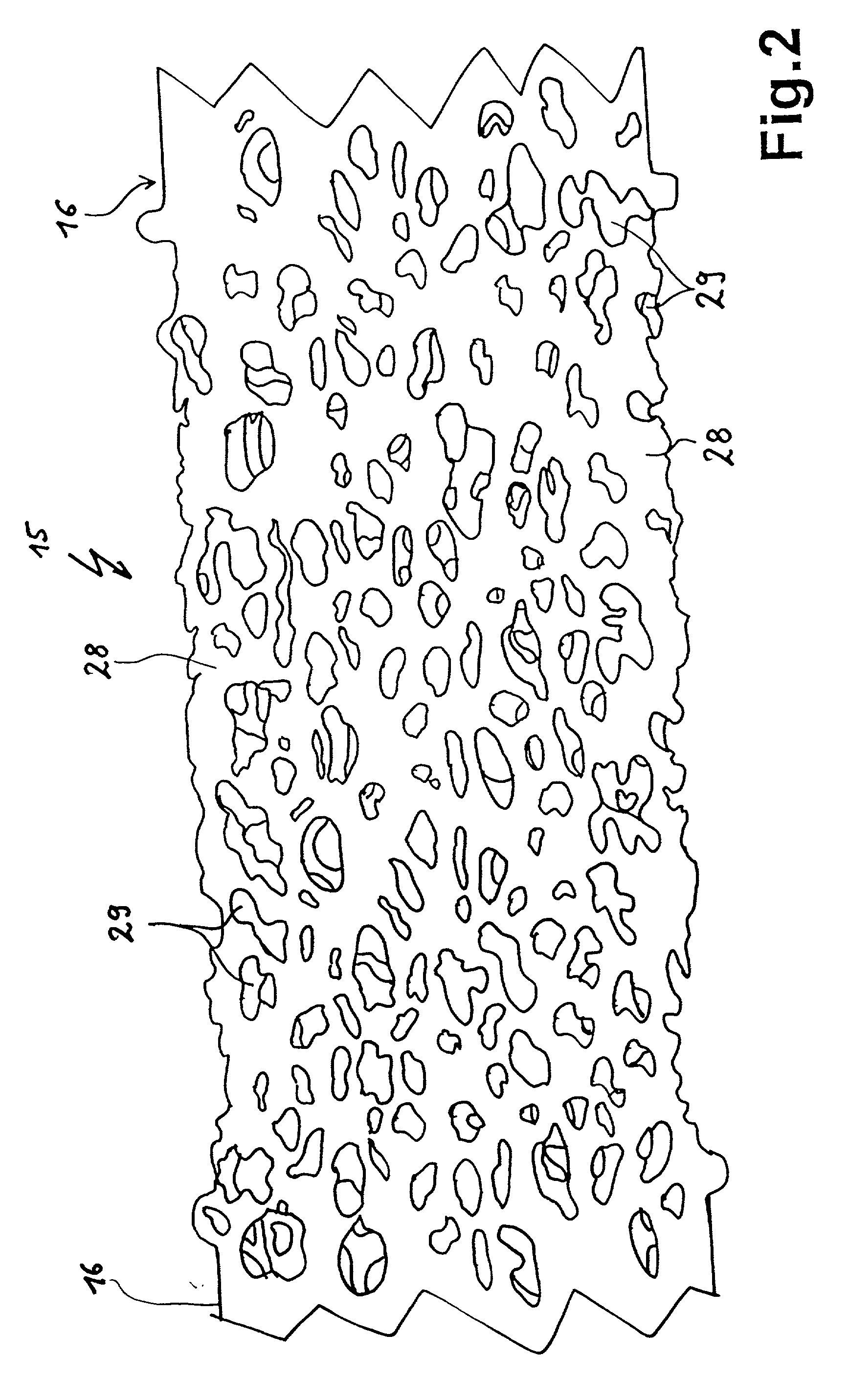
It is via the porosity of the foamed ceramic and its pore size and number or mesh size of a skeletonized structured ceramic that the effective cross-section and / or the electrical resistance of the heating element can be set, the more or larger the pores or meshes the greater is the surface per mass unit and thus the radiance although the limiting factors in this respect are the ruggedness of and volume taken up by the heating element.

Method used


Image

  • Electric heating element and method for its production
  • Electric heating element and method for its production
  • Electric heating element and method for its production

Examples


Embodiment Construction

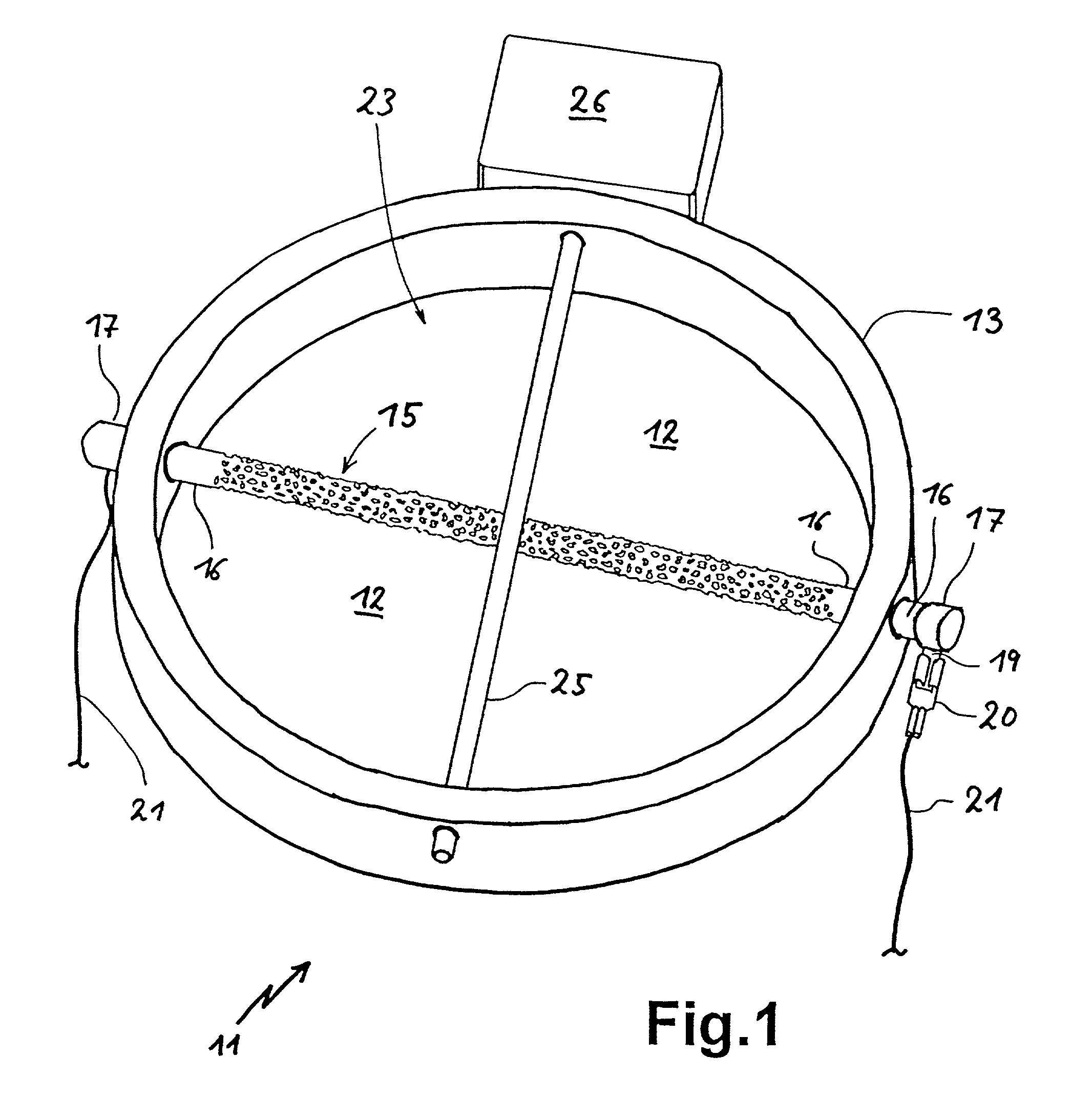
[0060] Referring now to FIG. 1 there is illustrated diagrammatically in a slanting view a radiant heater body 11 consisting of a dished insulator substrate 12 and a tubular insulating rim 13. Substrate 12 and rim 13 may be arranged, where necessary, in a supporting dish or the like, for example of thin sheetmetal.

[0061] Applied to the insulator substrate 12 is a heating element 15 in accordance with the invention forming the diameter of the round radiant heater body 11. The heating element 15 is illustrated rod-shaped, whereby of course, deviations from this shape may be provided. In addition, the heating element 15 is illustrated in this arrangement alone solely for a better overview, i.e. it being possible to advantage to provide further heating means. Further heating means could be, for example, further heating rods such as the heating element 15, or as an alternative thereto other radiant heater bodies such as radiant heater bands or bright radiators, e.g. halogen lamps. In such...


PUM

PropertyMeasurementUnit
temperature coefficientaaaaaaaaaa

Abstract

On the one hand is provided an electric heating element (15, 31) consisting of a semiconducting ceramic (28, 32) as well as a method for its production. The semiconducting ceramic material may be porous or foamed to thus contain pores (29, 34) open outwardly. The pores are attainable by admixing filler bodies, which dissolve during sintering, to the starting material or by impreganting a textile substrate material (36) with a ceramic material. Due to the porosity of the heating element (15, 31) an increased radiant surface area is attained. On the other hand is provided an electric heating element (115, 132, 145, 150, 158, 160, 162) as well as a method for its production which consists of semiconducting ceramic and comprises a negative temperature coefficient of the electrical resistance. The temperature coefficient is negative throughout over the full operating temperature range. The material suitable for the heating element (115, 132, 145, 150, 158, 160, 162) is doped silicon carbide or TiN. One such heating element (115, 132, 145, 150, 158, 160, 162) may be put to use, for example, rod-shaped in a radiant heater body (111) or foil-shaped at the underside of a surface element (30) of a cooktop (31). The electric conductivity of the material of the heating element (115, 132, 145, 150, 158, 160, 162) can be adjusted by nitrogen absorption during annealing in a nitrogen atmosphere subsequent to the sintering process.

Description

TECHNICAL FIELD AND BACKGROUND OF THE INVENTION[0001] The invention relates to an electric heating element, more particularly for a radiant heater body of an electric range made of a semiconducting ceramic, and to a method for its production.[0002] DE 296 19 758 U1 discloses an electric radiant heater including an electric resistance heating element comprising a changing temperature coefficient of the electrical resistance. In a first temperature range extending from 0.degree. C. to at least 700.degree. C. the temperature coefficient is negative. In a second temperature range following the first temperature range the temperature coefficient is required to be positive. In this way it is intended that the resistance heating element automatically adapts to the second temperature range or to automatically limit any further increase in temperature above a critical value after an initial very fast increase in temperature to red hot.[0003] The radiant heater takes the shape of at least one...

Claims


Application Information

Patent Timeline
Patent Type & Authority Applications(United States)
IPC IPC(8): H05B3/14H05B3/74
CPCH05B3/141H05B3/148H05B3/748H05B2203/019
Inventor OSE, LUTZWILDE, EUGENESSIG, WILLI
Owner E G O ELEKTRO GERAETEBAU GMBH
Learn More