Pumpjack dynamometer and method

a dynamometer and push rod technology, applied in the field of push rod dynamometers, can solve the problems of not always providing accurate or reliable information, adversely affecting the reliability of much of the sensing equipment, and being subject to wear and tear, etc., and achieve the effect of long-term calibration errors and high reliability

a dynamometer and push rod technology, applied in the field of push rod dynamometers, can solve the problems of not always providing accurate or reliable information, adversely affecting the reliability of much of the sensing equipment, and being subject to wear and tear, etc., and achieve the effect of long-term calibration errors and high reliability

US20010021347A1Inactive Publication Date: 2001-09-13MILLS MANUEL D

Image

  • Pumpjack dynamometer and method
  • Pumpjack dynamometer and method
  • Pumpjack dynamometer and method

Examples


Embodiment Construction

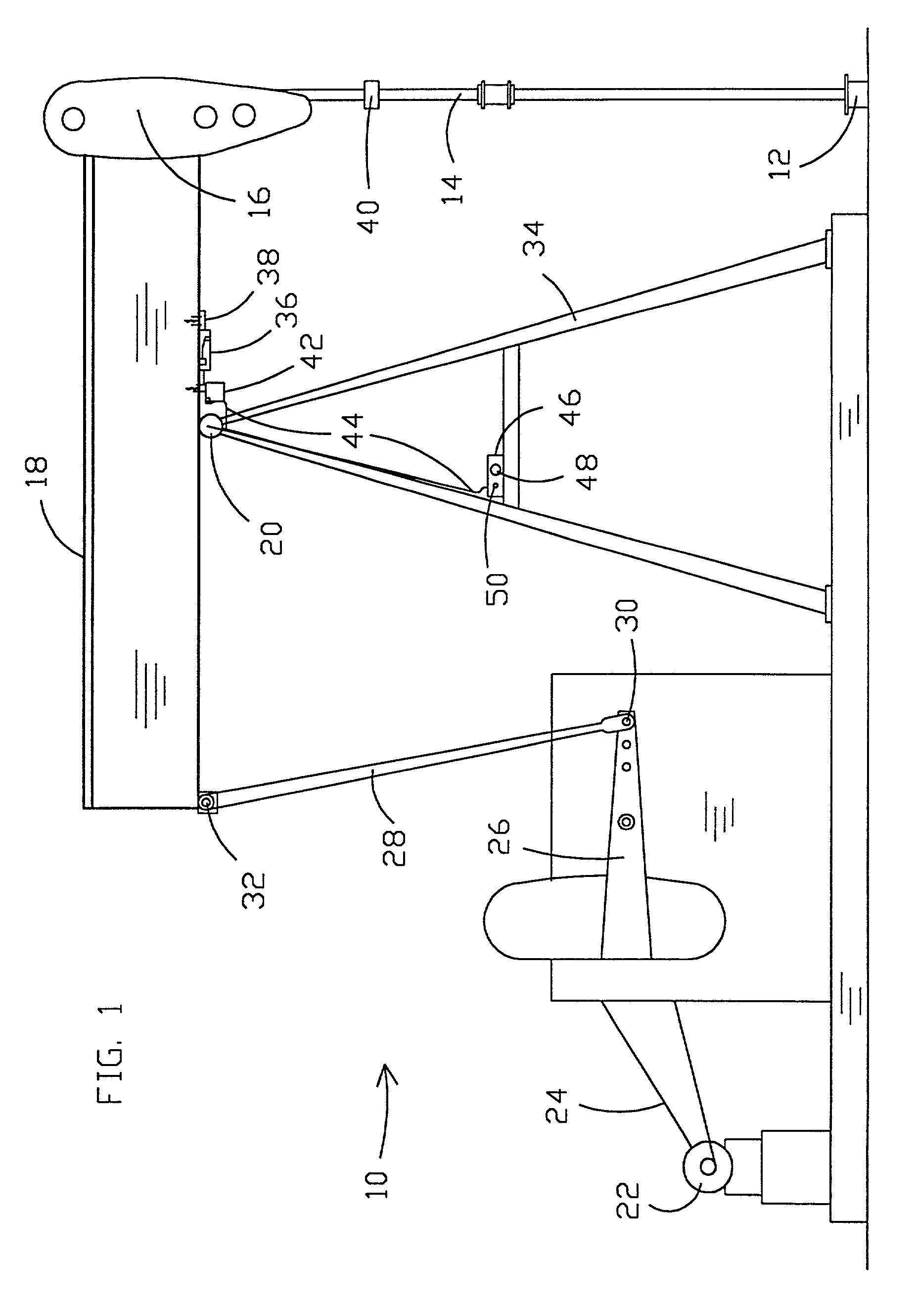
[0060] Referring now to the drawings, and more particularly to FIG. 1, a pumpjack unit 10 is shown in operative relationship respective to a wellhead 12. A downhole pump (not shown) is activated by reciprocal movement of sucker rod string (not shown) and polished rod 14 that is suspended from horse head 16. Horse head 16 is affixed to walking beam 18, which is a rigid beam that extends on either side of pivot connection 20. Walking beam 18 is reciprocated by a prime mover 22, which may typically comprise an electric motor. Prime mover 22 drives walking beam 18 through a drive system which may typically comprise elements such as drive belt 24, crank arm 26, drive arm 28 that is pivotally connected to walking beam 18 and crank arm 26 with pin connections 30 and 32. Walking beam 18 is pivotally supported by a suitable frame 34 such that walking beam pivots in two different directions, moving sucker rod string and polished rod 14 upwardly and downwardly during each pump stroke.

[0061] A ...


PUM


Abstract

A dynamometer readout (42, 46) and method is disclosed for obtaining dynamometer information (110) related to pumpjacks (10). For this purpose, a change of pivotal direction of the walking beam (18) may be detected by processor (82) utilizing an encoder component (60) with spaced slots (64) therein and light signal devices (68, 70, 72, 74) positioned to have a spacing different from that of the spacing of the slots (64). Software techniques filter out effects of stray mechanical vibrations. An infrared transceiver (46, 50, 100) of a preferred embodiment includes a radio frequency carrier generator (90) and modulator (88) that produces an infrared signal receivable by a low cost consumer radio receiver. The radio frequency modulation technique for infrared signals (96) and related filtering (98, 102, 104) condition formatted infrared signals for utilization in daylight and through a car window for drive-by downloading of data to second computer (108). A sensor (163) may be substituted for the encoder. A sensor (163) may include a moveable light interrupter, such as a ball (160) or a bubble (260), moveably disposed within the sensor. The sensor may also provide one or more apertures (180) for transmitting light through the apertures.

Description

1. FIELD OF THE INVENTION[0001] The present invention generally relates to pumpjack dynamometers and, more particularly, to apparatus and methods for producing and transmitting dynamometer card information.2. BACKGROUND OF THE INVENTION[0002] Dynamometers are commonly utilized in the oil field to monitor the operation of pumpjacks used to pump oil to the surface. The dynamometer card provides information related to pumping conditions as described in detail in subsequently listed patents. For instance, a typical use of such information involves determining when a well has reached what is known as a "pump-off" condition wherein the wellbore does not receive enough oil to fill the downhole pump during the entire pump stroke. Changes in the dynamometer card readings over time may be used to provide this information. It may be desirable to temporarily stop operating the pump until the pump off condition has been obviated by continued flow from the formation into the wellbore while the pu...

Claims


Application Information

Patent Timeline
13 Sep 2001
Publication
US20010021347A1
IPC
E21B47/00; F04B47/02; F04B49/06
CPC
E21B47/0006; E21B47/0008; F04B47/022; F04B49/065; E21B47/007; E21B47/009
Inventors
MILLS, MANUEL D.