Image rejection mixer

a technology of image rejection and mixer, which is applied in the field can solve the problems of large noise figure of image rejection mixer, high power dissipation, noise and distortion

Inactive Publication Date: 2001-10-04
RENESAS ELECTRONICS CORP
View PDF10 Cites 34 Cited by
  • Summary
  • Abstract
  • Description
  • Claims
  • Application Information

AI Technical Summary

Problems solved by technology

Since the CR lattice circuit is current-driven by a constant current source, however, power dissipation becomes high.
The transistor pair and the current source may cause noise and distortion.
If the noise or the like occurs, the noise figure of the image rejection mixer becomes large and the reception sensitivity becomes worse in some cases.
If it is attempted to input a greater DC current, however, the power dissipation in the image rejection mixer becomes higher.

Method used


Image

  • Image rejection mixer
  • Image rejection mixer
  • Image rejection mixer

Examples


first embodiment

[0027] (First Embodiment)

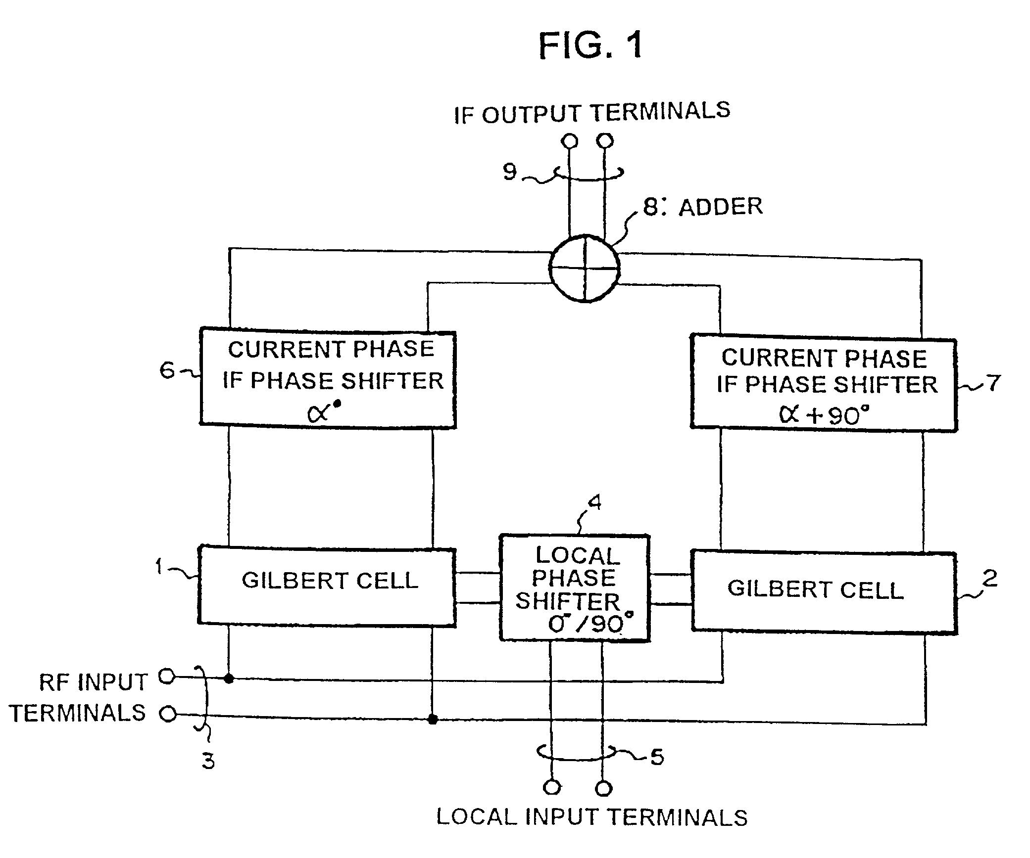
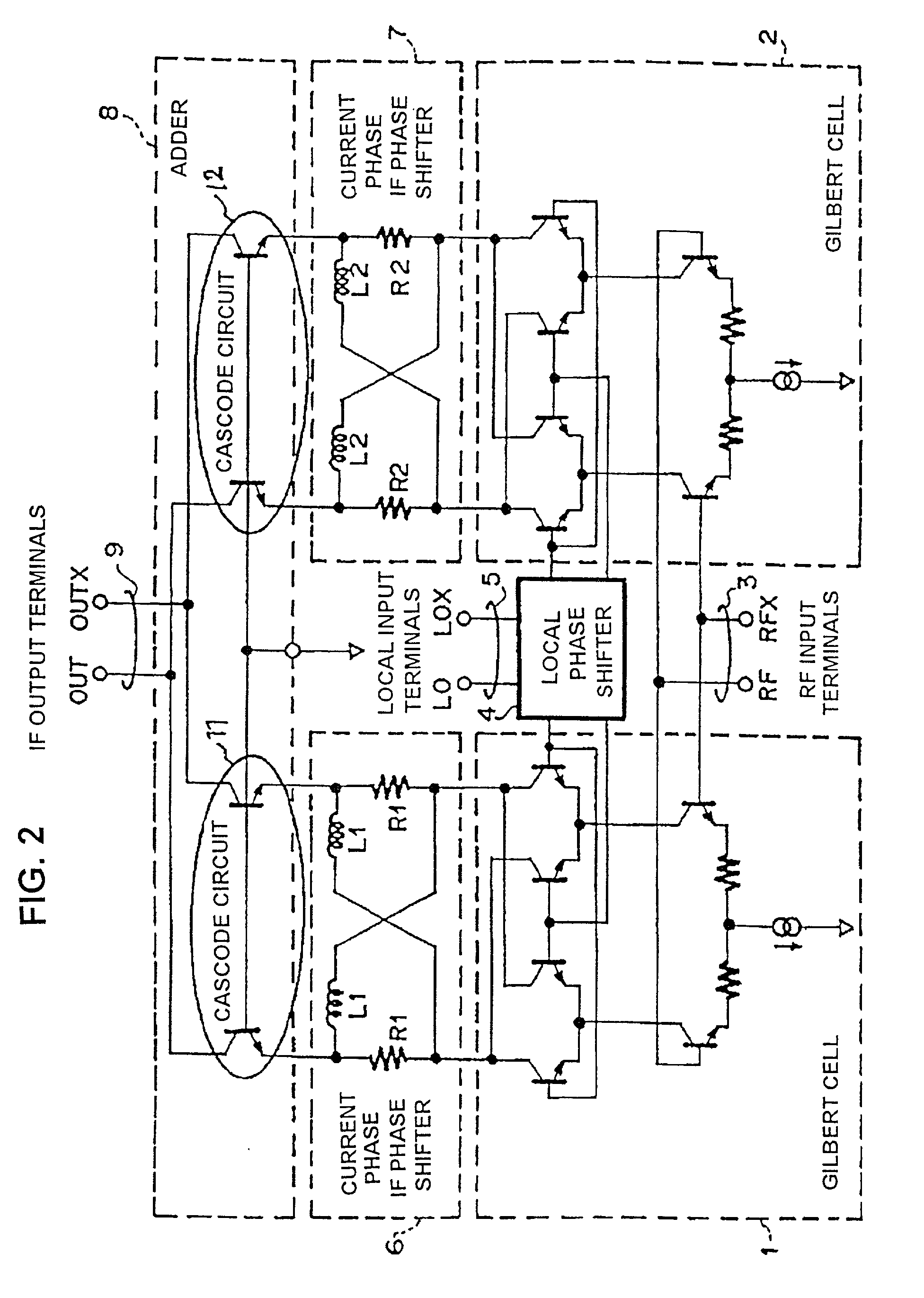
[0028] FIG. 1 is a block diagram of an image rejection mixer according to a first embodiment of the present invention. FIG. 2 is an equivalent circuit diagram of the image rejection mixer shown in FIG. 1.

[0029] In FIGS. 1 and 2, there are shown local input terminals 5 for inputting local signals LO and LOX having, for example, a phase difference of 90.degree., a local phase shifter 4 for outputting the local signal LO and the local signal LOX with the same phase and shifting them in phase by 90.degree. and outputting resultant signals, radio frequency (RF) input terminals 3 for inputting an RF signal and an RFX signal which have an image RF signal and have a phase difference of, for example, 90.degree., and double smoothing mixers such as Gilbert cells 1 and 2 for mixing the RF signal and the RFX signal with output signals of the local phase shifter 4 and outputting an IF current signal.

[0030] Furthermore, there are also shown in FIGS. 1 and 2, intermediate ...

second embodiment

[0048] (Second Embodiment)

[0049] FIG. 4 is an equivalent circuit diagram of an image rejection mixer of a second embodiment according to the present invention. FIG. 4 corresponds to FIG. 2 of the first embodiment. In FIG. 4, an adder 8 is different from that shown in FIG. 2. To be concrete, the adder 8 includes differential amplifiers each having a positive feedback loop designed so as not to cause signal oscillation.

[0050] As shown in FIG. 4, the adder 8 including differential amplifiers each having a positive feedback loop can be made nearly 0 in input impedance, and consequently the current gain can be made large. Furthermore, when the IF phase shifters of current phase type 6 and 7 are driven, a phase shift amplitude error actually occurs. The phase shift amplitude error can be reduced by the positive feedback loop.

third embodiment

[0051] (Third Embodiment)

[0052] FIG. 5 is a block diagram of an image rejection mixer of a third embodiment according to the present invention. FIG. 5 corresponds to FIG. 1 of the first embodiment. In FIG. 5, impedances Z1 and Z2 each including, for example, a resistor, a capacitor, and an inductor, or an arbitrary combination of them are provided between the Gilbert cells 1 and 2 and the IF phase shifters of current phase type 6 and 7 in order to reduce the phase error in the Gilbert cells 1 and 2.

[0053] In the IF phase shifters of current phase type 6 and 7, the input signals are shifted in phase by .alpha. degrees and (.alpha.+90) degrees, respectively. Therefore, the values of the inductors L1 and L2 and the resistors R1 and R2 are different. Therefore, the LR lattice circuits respectively included in the IF phase shifters of current phase type 6 and 7 are different in impedance. By the influence of the parasitic effect, therefore, phase errors occur in the Gilbert cells 1 and 2...


PUM


Abstract

An object of the present invention is to lower the power dissipation of the image rejection mixer. The image rejection mixer includes distribution means supplied with local signals having a phase difference to distribute the local signals, first and second mixing means for mixing the distributed local signals and RF signals having a phase difference and outputting respective IF current signals, phase shift means for shifting in phase the respective mixed IF current signals so as to provide them with a relative phase difference of 90 degrees, and addition means for adding the respective phase shifted intermediate frequency current signals. The phase shift means shifts the phases of the respective IF current signals outputted from the first and second mixing means.

Description

[0001] 1. Technical Field of the Invention[0002] The present invention relates to an image rejection mixer, and a receiver using the mixer.[0003] 2. Description of the Prior Art[0004] Conventionally, many of receivers such as radio communication devices have an image rejection mixer for removing an image signal component out of a received radio frequency signal. Hereafter, the conventional image rejection mixer will be described by referring to the drawing.[0005] FIG. 6 is a block diagram of an image rejection mixer device described in JP 10-190359 A (1998). FIG. 7 is an equivalent circuit diagram of phase shifters of the image rejection mixer device shown in FIG. 6. The phase shifters include CR lattice circuits each having capacitors C and resistors R.[0006] As for local oscillator signals to be applied to two mixers 101 and 102 in the image rejection mixer device shown in FIG. 6, a signal supplied from a common local oscillation source is shifted in phase by +4.degree. and -45.de...

Claims


Application Information

Patent Timeline
Patent Type & Authority Applications(United States)
IPC IPC(8): H03D7/14H03H7/18H03D7/16H03D7/18H03H11/02H04B1/26H04B1/28
CPCH03D7/1433H03D7/165H03D7/18H04B1/28H03D7/1458H04N5/44
Inventor WANG, JIANQIN
Owner RENESAS ELECTRONICS CORP
Why Eureka
Try Eureka