
Line driver

a line driver and driver technology, applied in the field of line drivers, can solve the problems of power dissipation, limited power reduction possibilities of line drivers, and substantial power dissipation in line drivers

Inactive Publication Date: 2001-10-11
TELEFON AB LM ERICSSON (PUBL)
View PDF0 Cites 27 Cited by
  • Summary
  • Abstract
  • Description
  • Claims
  • Application Information

AI Technical Summary

Benefits of technology

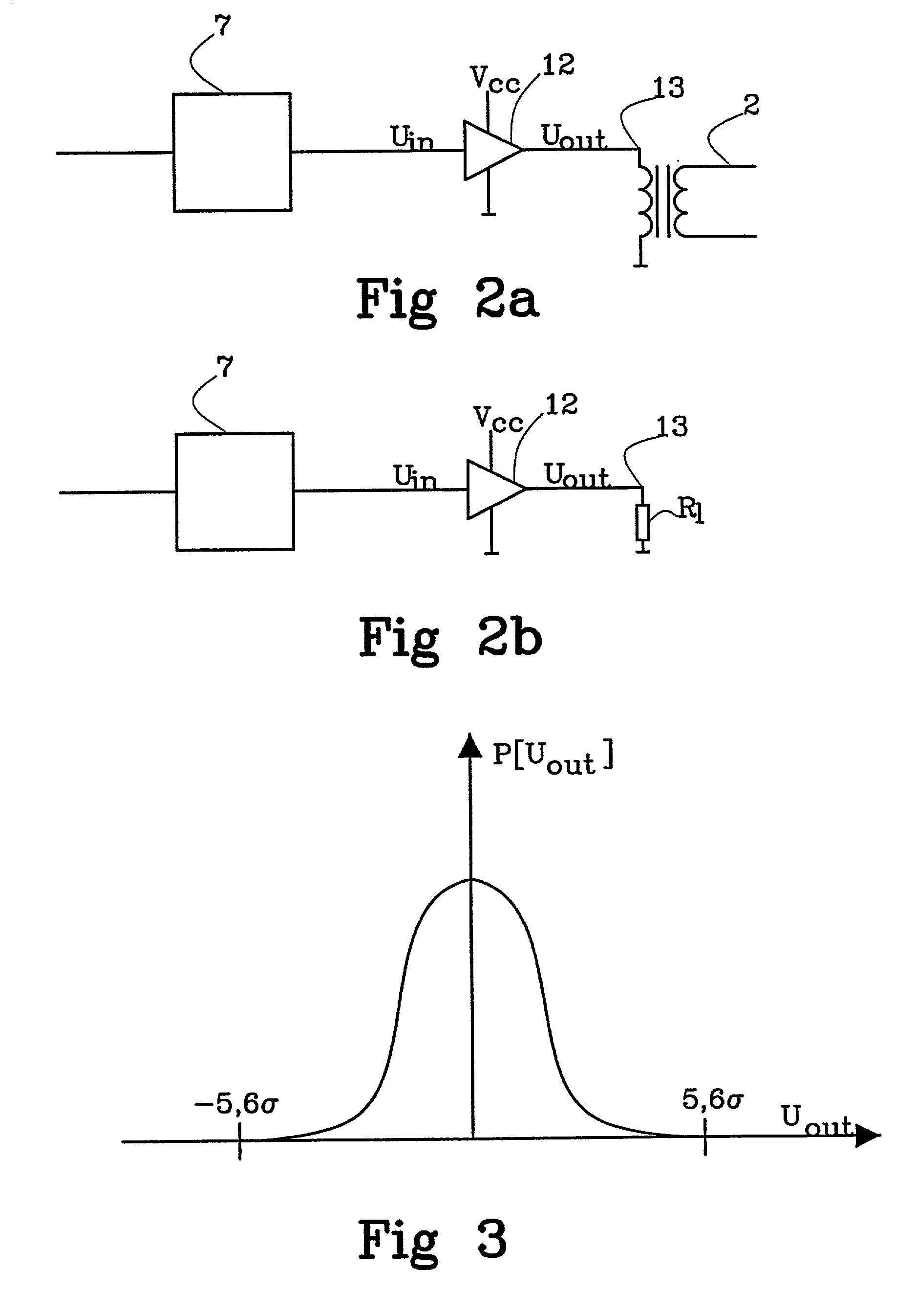
[0014] The advantages are that a low power dissipation and a stable idle voltage is achieved in a simple circuit without the need for many power supplies. The larger the differences of probability are within the range compared to outside the range the larger is the gain of lowered power dissipation. This is particularly evident in e.g. systems with Gaussian distributed input voltage probabilities, such as is the case for a line driver in a multicarrier system.

Problems solved by technology

Unfortunately, such a high supply voltage results in substantial power dissipation in the line driver.
Power dissipated in digital logic will be possible to reduce in the future by improved semiconductor technology, but physical laws limits the possibilities to reduce the power in the line driver.
The problem with this embodiment is that when the amplifier is in an idle mode, it will take an idle voltage in the middle of the voltage range.
This is bad, because then the output voltage will change when the power supply voltage is changed, even though it is supposed to be an idle mode.
Another problem is that it is necessary to use two different power supplies, which is expensive, inefficient and place consuming.
This makes the idle voltage at zero at all times. The problem with this embodiment is that as many as four different power supplies are needed.

Method used


Image

  • Line driver
  • Line driver
  • Line driver

Examples


Embodiment Construction

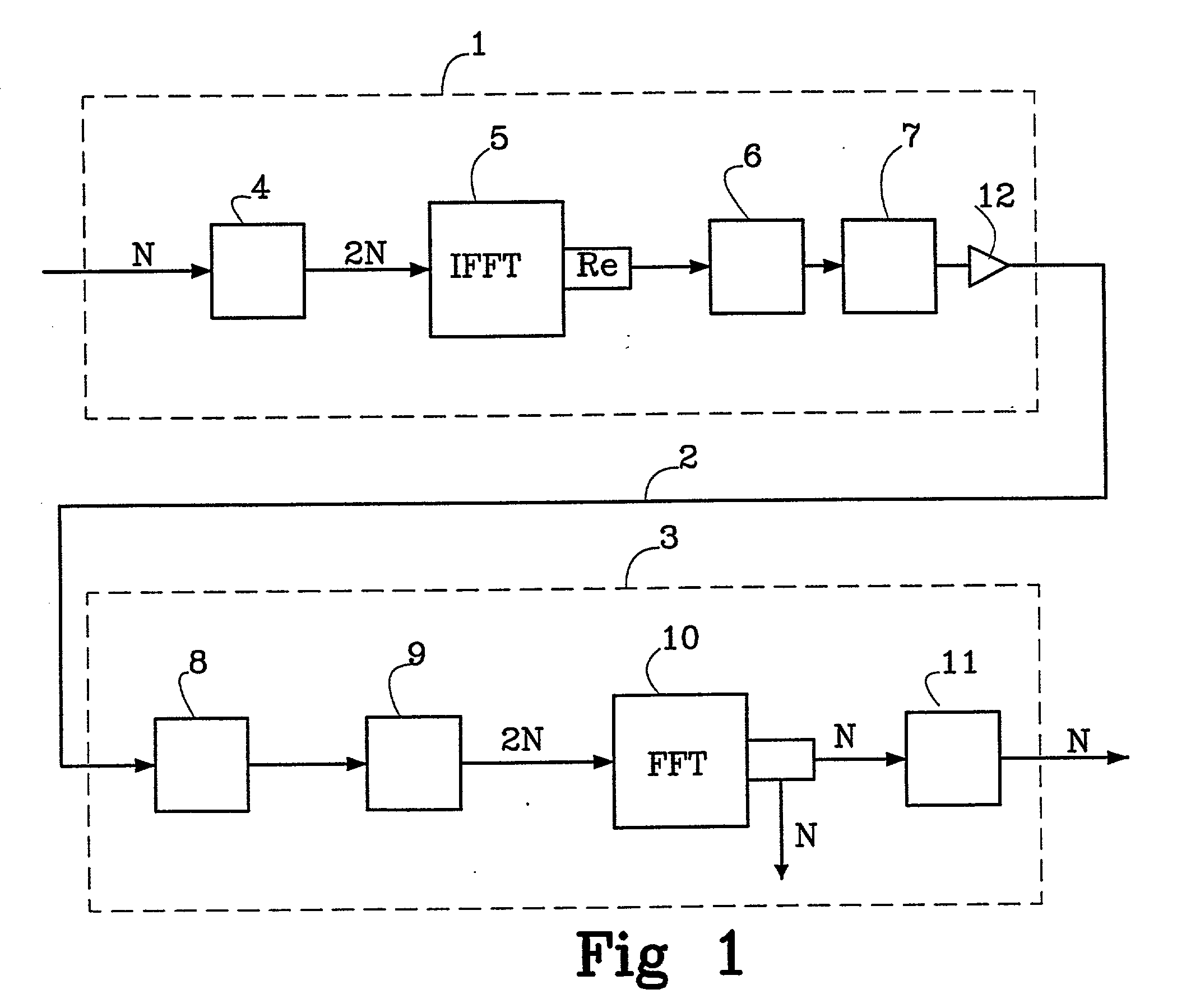
[0025] FIG. 1 shows, schematically, how the main parts of a prior art system for multi-carrier modulation may look. In a transmitter 1 modulation of data bits, for example from a digitally encoded video signal, is performed.

[0026] The bits to be transmitted are encoded in the transmitter 1 as N complex numbers before a hermit symmetry operation is carried out in a calculation block 4. 2N complex numbers are obtained having a symmetric real part and an asymmetric imaginary part.

[0027] An Inverse Fast Fourier Transform (IFFT) is then performed in an IFFT calculation unit 5, as a modulation. Since the imaginary part becomes zero it may be eliminated and a real signal remains, which passes a parallel to serial converter 6, a digital-to-analogue converter 7 and a line driver 12.

[0028] This gives a sum of orthogonal carriers or tones, the amplitudes and phases of which are determined by the values and phases of the original complex numbers. These carriers are then transmitted in a line 2 ...


PUM


Abstract

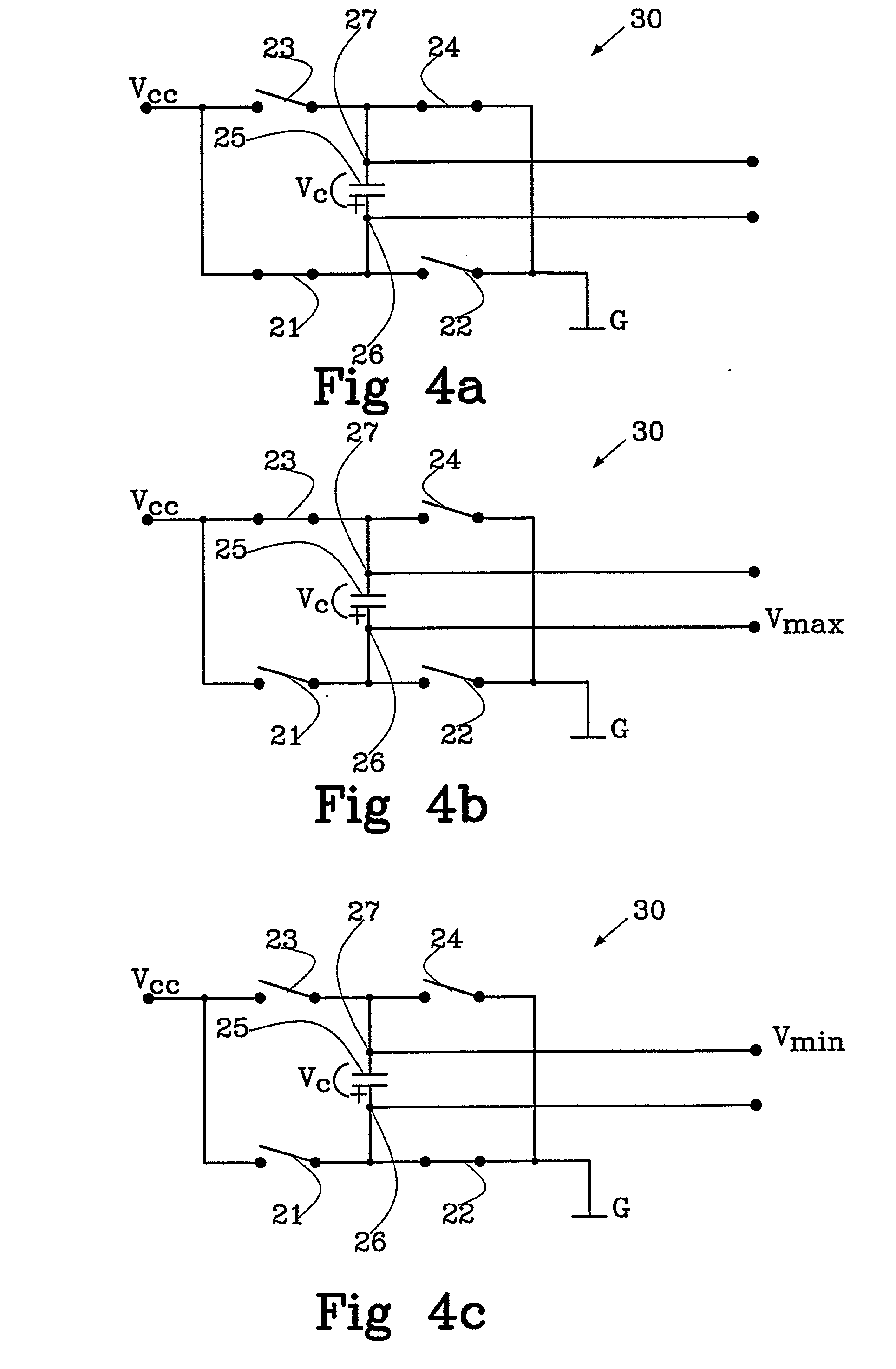
The invention relates to a line driver supplied with a power supply voltage from a power supply and an amplifying method. According to the invention the following steps are performed: using whole or part of the power supply voltage to generate the output voltage if the input voltage is within the predefined range; loading at least one capacitor with at least one capacitor voltage; and using whole or part of the capacitor voltage in addition to whole or part of the power supply voltage to generate the output voltage if the input voltage is outside the predefined range.

Description

[0001] The present invention relates to a line driver and an amplifying method in said line driver.Description of Related Art[0002] Multi-carrier modulation is a known method for transmitting broadband information (for example, video, Internet or telephony) over radio connections or copper wire. The latter may be e.g. XDSL systems, such as Asymmetric Digital Subscriber Line (ADSL), High-rate Digital Subscriber Line (HDSL) or Very high speed asymmetric Digital Subscriber Line (VDSL). Two similar methods in multi-carrier modulation are Orthogonal Frequency Division Multiplex (OFDM), used in radio applications, and Discrete Multitone (DMT), which is used in copper wires.[0003] Very briefly explained, the bits that are to be transmitted, (of for example a digitally encoded video signal) are encoded as complex numbers in a transmitter. In the transmitter an Inverse Fast Fourier Transform (IFFT) and a digital-to-analogue conversion are carried out whereupon the result is sent out on a lin...

Claims


Application Information

Patent Timeline
Patent Type & Authority Applications(United States)
IPC IPC(8): H03K19/00H03K19/013H04L27/00H04L27/26
CPCH03K19/0008H03K19/0136H04L27/0002H04L27/2626H04L27/2614
Inventor ANDRE, TORE
Owner TELEFON AB LM ERICSSON (PUBL)
Learn More