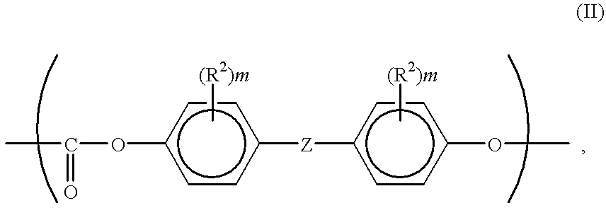
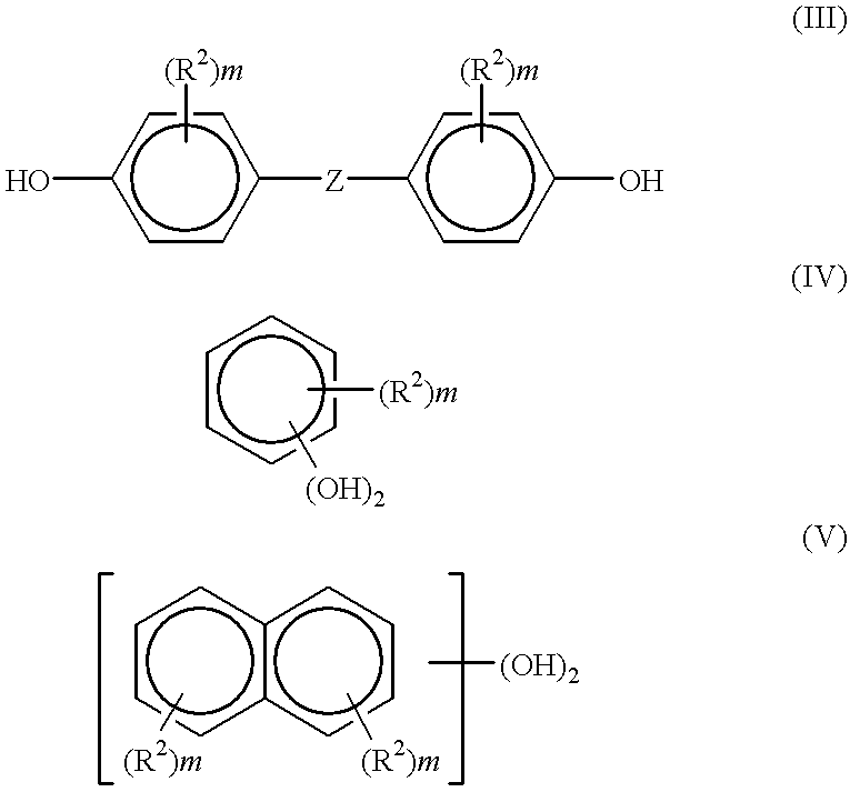
On the other hand, if the transfer condition is optimized for a thin paper, the
transfer efficiency or rate of a toner image from the electrostatic image-bearing member to a transfer material is lowered, thus resulting in difficulty with respect to
image density or resolution, when a thick paper or an OHP film is used.
Particularly, in a monocomponent developing scheme wherein a toner in a form of so-called "ear" or chains is used for development, the resolution in the lateral image direction is liable to be inferior than in the longitudinal direction.
Further, compared with a
solid image, line images are liable to be developed with a larger amount of attached toner, thus increasing the toner consumption to result in inferior image reproducibility and economical performance.
Moreover, in the development with a toner, there are liable to occur difficulties such as a tailing phenomenon that the toner protrudes in its ear form out of the image portion, or toner scattering around the image region, thus providing another factor of lowering the resolution.
However, when a conventional toner is applied to this scheme, a large stress is exerted to both the toner particles and the toner-carrying member surface, thus resulting in difficulties, such as toner surface deterioration, soiling or toner sticking on the toner-carrying member surface, and difficulty in matching with the image forming apparatus.
Further, JP-A 63-235953 has proposed a magnetic toner sphered by application of a
mechanical impact, whereby the transferability has been improved to some extent but the improvement is not sufficient, and the developing performance has not reached a level of accomplishing a sufficiently
high definition.
These toners are still companied with difficulties of
image quality lowering due to toner deterioration and transferability and also a difficulty that, in a low temperature / low
humidity environment, the developing performance is lowered due to excessive toner charge, resulting in a remarkably lower resolution.
% of particles having a circularity of at most 0.85, whereby improvements in flowability, quick charging performance and
cleanability with a cleaning blade are referred to, whereas no care has been taken regarding continuous image forming performance and
environmental stability accompanying the decrease in particle size, thus not accomplishing a sufficiently
high resolution.
The developer exhibits some improvement in providing
image density stability, but no care has been taken regarding a
small particle size having a 50%-
average diameter of below 8 .mu.m and an average circularity exceeding 0.96, thus leaving room for improvements in the above-mentioned problems.
However, according to such a roller transfer scheme not using
corona discharge wherein a transfer charging member is pressed against a photosensitive member (electrostatic image-bearing member) via a transfer material at the time of transfer, a toner image on the photosensitive member is compressed at the time of transfer onto the transfer material, thereby causing a partial transfer failure so-called "hollow image" or "transfer dropout".
Further, in such a roller charging scheme, physical and
chemical actions of
discharge occurring between the charging roller and the photosensitive member become intense than in the
corona charging scheme, so that the photosensitive member surface is liable to be worn due to deterioration of the photosensitive member surface, thus leaving a problem regarding the life of the photosensitive member, especially in the combination of an organic photosensitive member and a blade cleaning member.
Accordingly, comprehensive studies further inclusive of one on developing performance are being made but they are not yet sufficient.
However, it is a general tendency that, when toner particles are reduced in particle size, the proportion of fine particle size toner is naturally increased, so that the uniform charging of toner particles becomes difficult to result in image
fog and the toner attachment force onto the surface of the electrostatic image-bearing member increases to result in an increased amount of transfer residual toner.
If the average circularity exceeds 0.995, the toner surface deterioration becomes pronounced, to result in a problem in continuous image forming performance.
If the
residual monomer content in the toner exceeds 500 ppm, the toner becomes problematic in respects of chargeability and anti-blocking property.
If the theoretical
glass transition temperature is below 40.degree. C., the
resultant toner is liable to suffer from difficulties with respect to storage stability and continuous image forming stability.
This is particularly undesirable for color toners for forming full-color images, as the color mixability of the respective color toners is lowered to result in inferior color reproducibility and OHP images with lowered transparency.
If the peak molecular weight is below 1000, the chargeability of the
resultant toner can be adversely affected in some cases.
In excess of 5.times.10.sup.5, the molt-
viscosity becomes excessive, and the fixability of the toner can be adversely affected in some cases.
ited. In excess of 50 wt. parts, some difficulties may be encountered with respect to the chargeability, fixability and matching with image forming app
According to the pulverization process for toner production, it is difficult to obtain toner particles having a circularity in the prescribed range.
According to the melt-spraying process, the resultant toner particles are liable to have a broad
particle size distribution even if they have a certain level of circularity, and it is difficult to provide toner particles with an adequately controlled surface state.
If the gap is narrower than 100 .mu.m, the supply of the developer is liable to be insufficient to result in a low
image density.
In excess of 1000 .mu.m, the lines of magnetic force exerted by a developing pole S1 is spread to provide a
low density of magnetic
brush, thus being liable to result in an inferior dot reproducibility and a weak carrier constraint force leading to carrier attachment.
If the application
voltage is below 500 volts it may be difficult to obtain a sufficient image density and
fog toner on a non-image region cannot be satisfactorily recovered in some cases.
Above 5000 volts, the
latent image can be disturbed by the magnetic
brush to cause lower image qualities in some cases.
The frequency can affect the process, and a frequency below 500 Hz may result in
charge injection to the carrier, which leads to lower image qualities due to carrier attachment and latent image disturbance, in some cases.
Above 10000 Hz, it is difficult for the toner to follow the
electric field, thus being liable to cause lower image qualities.
If the developing nip C is narrower than 3 mm, it may be difficult to satisfy a sufficient image density and a good dot reproducibility.
If broader than 8 mm, the developer is apt to be packed to stop the movement of the apparatus, and it may become difficult to sufficiently prevent the carrier attachment.
In case where the
surface roughness Ra of the toner carrying member exceeds 1.5, it become difficult to form a
thin layer of toner on the toner carrying member and improve the toner chargeability, so that the improvement in
image quality becomes difficult to realize.
If the surface speed of the toner carrying member is below 1.05 times that of the electrostatic image-bearing member, such a toner layer stirring effect is insufficient, so that it becomes difficult to expect a
good image formation.
Further, in the case of forming a
solid image requiring a large amount of toner over a
wide area, the toner supply to the electrostatic image is liable to be insufficient to result in a lower image density.
On the other hand, in excess of 3.0, the toner is liable to be excessively charged and cause difficulties, such as toner deterioration or sticking onto the toner-carrying member (developing sleeve).
If the abutting pressure is below 0.1 kg / m, the uniform toner application becomes difficult to result in a broad toner charge distribution leading to
fog and scattering.
Above 25 kg / m, an excessive pressure is applied to the toner to cause toner deterioration or toner agglomeration, and a large torque becomes necessary for driving the toner-carrying member.


