
Alumina sintered compact and method of producing the same, and article for heat treatment using alumina sintered compact

a technology of alumina sintered compact and alumina sintered, which is applied in the direction of lighting and heating apparatus, instruments, furniture, etc., can solve the problems of deterioration of sintered compact, strength and creep characteristics of sintered compact, and shortened life of heat treatment firing tools or tubes in some cases

Inactive Publication Date: 2001-11-22
MURATA MFG CO LTD
View PDF0 Cites 13 Cited by
  • Summary
  • Abstract
  • Description
  • Claims
  • Application Information

AI Technical Summary

Benefits of technology

[0010] Under these circumstances, accordingly, an object of the present invention is to provide an alumina sintered compact that can prevent the accumulation of PbO on its surface while controlling the absorption of PbO, an article for heat treatment using the alumina sintered compact, and a method of producing the alumina sintered compact.
[0011] The present inventors made investigations on the crystal structure of an alumina sintered compact from the viewpoint of preventing the accumulation of PbO while controlling the absorption of, for example, PbO. They found that the corrosion resistance to, for example, PbO is improved when the surface area of the alumina sintered compact is composed of a layer of alumina crystal grains which have a large mean grain size and are obtained by grain growth, and that the accumulation of, for example, PbO on the surface area can be prevented by allowing the inside of the sintered compact to absorb and disperse PbO or the like attached to the surface area. The present invention has been accomplished based on these findings.

Problems solved by technology

However, when a ceramic article containing PbO, for example, is fired using a firing tool composed of the fine-grain-containing alumina sintered compact, the sintered compact is deteriorated due to the PbO, and the life of the firing tool or tube for heat treatment is shortened in some cases.
The strength and creep characteristics of the sintered compact are thus deteriorated to thereby invite warpage and deformation.
(1) The PbO absorption by the alumina sintered compact gradually decreases and the atmosphere varies every time the sintered compact is used.
(2) The sintered compact has a large amount of PbO on its surface, which PbO is liable to react with the ceramic article and adversely affects the quality of the ceramic article in some cases.
(3) PbO accumulated on the surface area expands and contracts in repeated heat cycles, and the crystal grains on the surface area may therefore peel or drop off to thereby invite the formation of a rough surface or depressions on the surface of the alumina sintered compact.

Method used


Image

  • Alumina sintered compact and method of producing the same, and article for heat treatment using alumina sintered compact
  • Alumina sintered compact and method of producing the same, and article for heat treatment using alumina sintered compact

Examples


experiment 1

[0052] Experiment 1

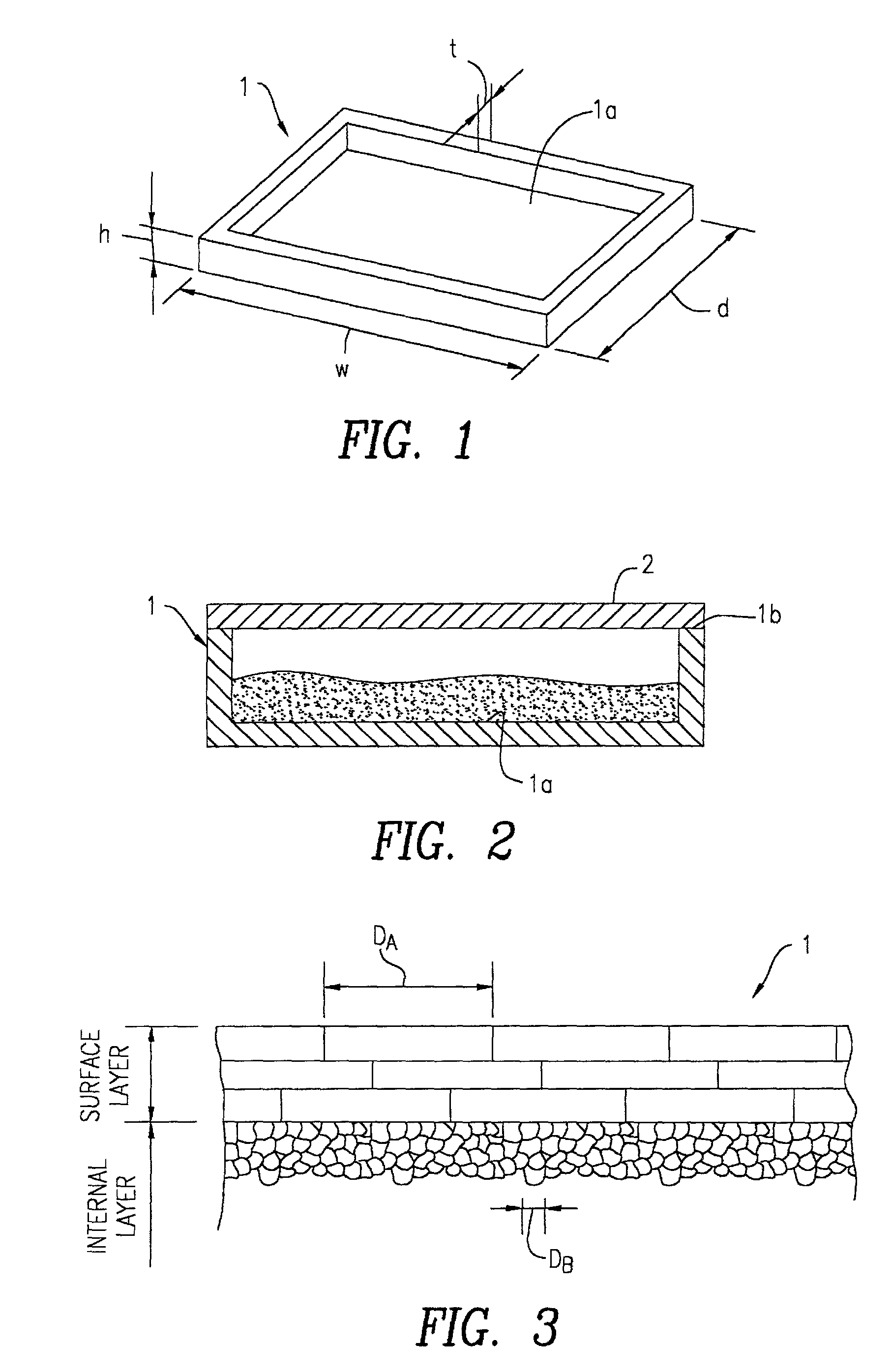
[0053] In this experiment, the cross section of bottom 1a (see FIGS. 1 and 2) of each of Samples No. 1* to No. 7 was observed with a scanning electron microscope to determine the thickness and mean grain size of the surface layer and the mean grain size of the internal layer.

[0054] In Table 1, Sample No. 4, in which alumina powder A and alumina powder B were mixed in a ratio of 1:1, had the surface layer formed overall in the thickness direction and had no internal layer. This is probably because the ratio of plate alumina powder A was excessively high. Separately, Sample No. 5, in which granular alumina powder B alone was used, naturally had the internal layer alone.

[0055] Sample No. 6, in which alumina powder A was mixed with alumina powder B in a ratio of 1:1 and the mixture was fired at 1500.degree. C., had the internal layer alone and no grain growth occurred. This is probably because the firing temperature was excessively low. Sample No. 7, in which powder A...

experiment 2

[0057] Experiment 2

[0058] Alumina powder A and alumina powder B were mixed in the same ratios as in the above samples according to the present invention, and each of the resulting mixtures was molded by dry press molding, wet press molding, extrusion molding, injection molding or doctor blade process to yield a series of sintered compacts. Each of the samples prepared by the above techniques had no crystal structure composed of a surface layer and an internal layer.

experiment 3

[0059] Experiment 3

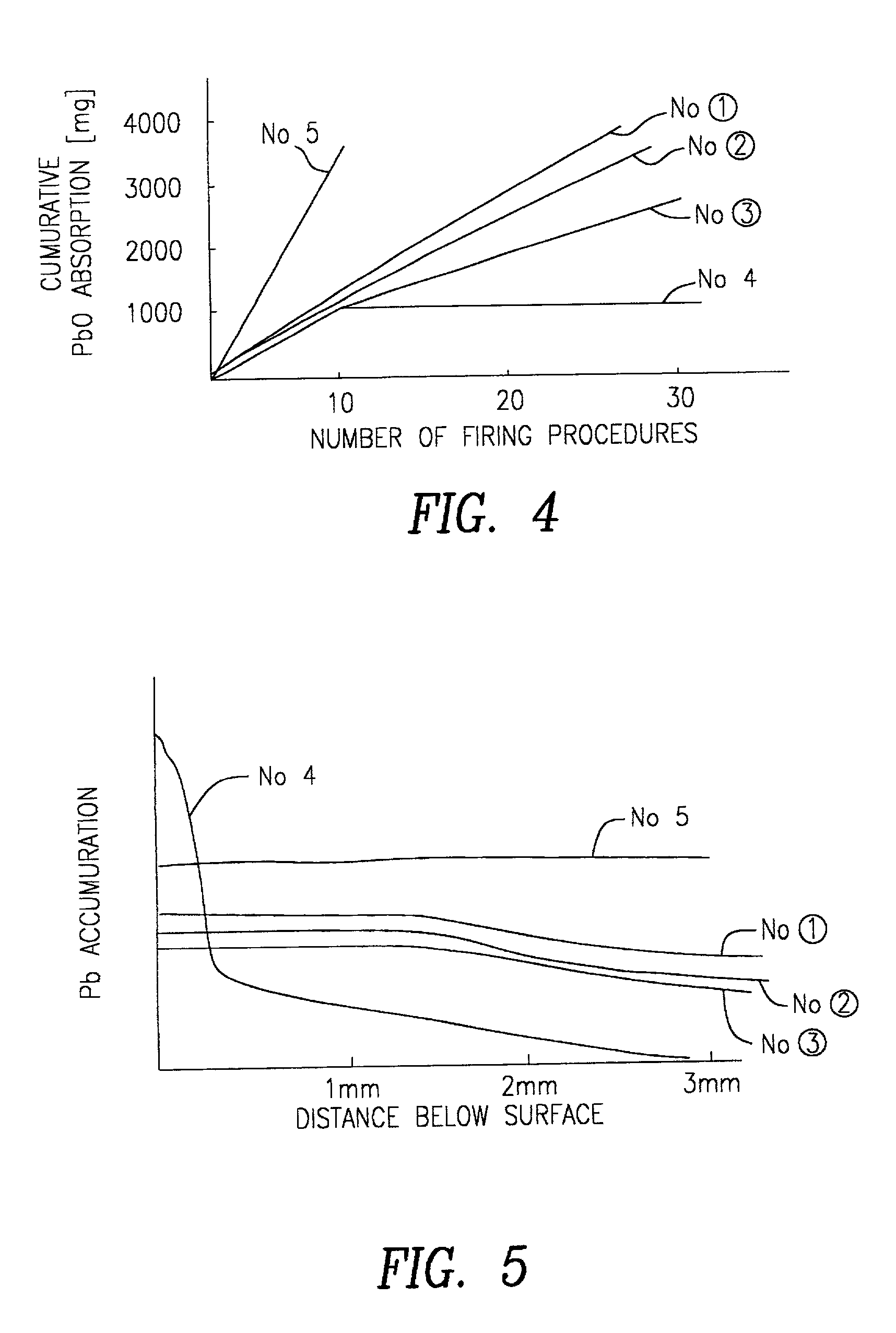
[0060] In this experiment, the cumulative PbO absorption of each of Samples No.1 * to No. 5 was determined in the following manner. As shown in FIG. 2, frame top face 1b of tool material 1 was ground, and the opening of tool material 1 was sealed with Al.sub.2O.sub.3 dense plate 2, 50 g of a PbO powder was then placed in tool material 1 and the powder was fired at 1300.degree. C. for 2 hours. This cycle was repeated 30 times, and tool material 1 was weighed after each firing procedure to determined the cumulative PbO absorption. The results are shown in FIG. 4.

[0061] FIG. 4 shows that the PbO absorption was high and the tool material became unworkable after about tenth firing procedure in conventional Sample No. 5 having the internal layer alone. In conventional Sample No. 4 in which grain growth occurred overall in the thickness direction, the PbO absorption reached the maximum of 1000 mg after about tenth firing procedure, indicating that repeated firing procedu...


PUM

PropertyMeasurementUnit
Fractionaaaaaaaaaa
Fractionaaaaaaaaaa
Fractionaaaaaaaaaa

Abstract

An alumina sintered compact includes at least two layers including an internal layer and a surface layer formed on the surface of the internal layer, which internal layer is composed of alumina crystal grains formed by sintering of a fine alumina powder, and which surface layer is composed of alumina crystal grains formed by grain growth of a fine alumina powder and having a mean grain size larger than that of the alumina crystal grains of the internal layer. This alumina sintered compact can prevent the accumulation of PbO in a surface area while controlling the absorption of PbO.

Description

[0001] 1. Field of the Invention[0002] The present invention relates to an alumina sintered compact obtained by firing an alumina powder, and a method of producing the same, and an article for heat treatment using the alumina sintered compact.[0003] 2. Description of the Related Art[0004] Alumina sintered compacts have satisfactory corrosion resistance and heat resistance and are generally used as firing tool materials such as boxes and cases or as tubes for heat treatment of items such as atmospheric gas supply tubes. This type of alumina sintered compacts includes a fine-grain-containing alumina sintered compact obtained by sintering a fine alumina powder, as described in Japanese Unexamined Patent Application Publication No. 4-231370, and an oriented alumina sintered compact obtained by firing a plate fine alumina powder to thereby the subject crystal grains to grain growth in layers, as described in Japanese Unexamined Patent Application Publication No. 7-315915.[0005] However, ...

Claims


Application Information

Patent Timeline
IPC IPC(8): C04B35/00C04B35/101C04B35/10C04B35/111F27D1/00
CPCC04B35/10C04B35/111F27D1/0006Y10T428/24942Y10T428/24975Y10T428/265Y10T428/252Y10S425/029
Inventor HIRAKO, KOICHIROUENO, KENJISUZUKI, TOMONOBU
Owner MURATA MFG CO LTD
Learn More