
Process and apparatus for producing iron carbide

a technology of iron carbide and process, applied in the direction of chemistry apparatus and processes, furnace types, furnace types, etc., can solve the problems of high equipment cost, high equipment cost, and high cost of steel making process through blast furnace, so as to reduce the gas temperature introduced, reduce the concentration of methane, and improve the effect of production efficiency

Inactive Publication Date: 2001-12-06
JP STEEL PLANTECH +1
View PDF0 Cites 9 Cited by
  • Summary
  • Abstract
  • Description
  • Claims
  • Application Information

AI Technical Summary

Benefits of technology

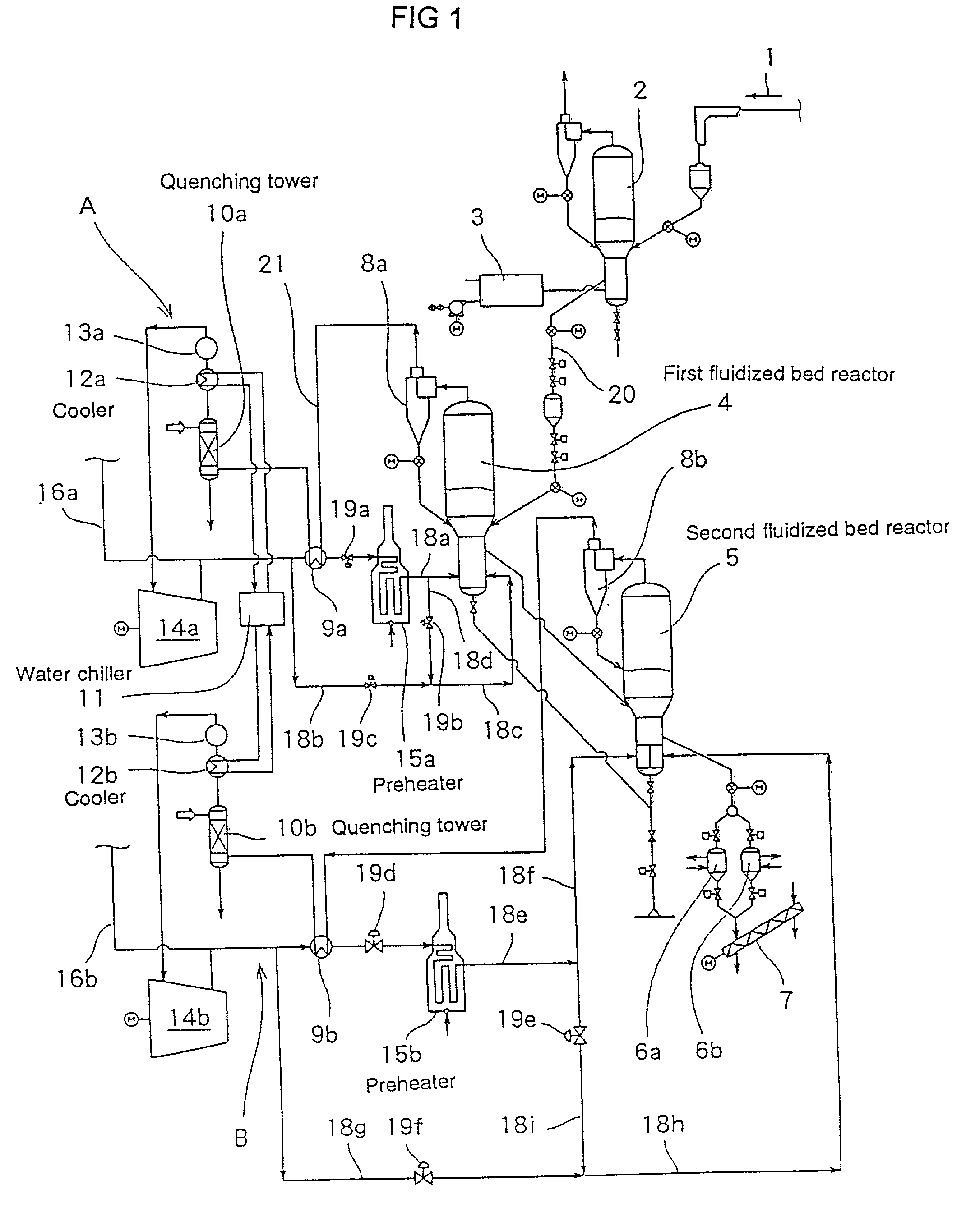
[0026] (d) one or more than two of gas circulation loop having a quenching tower and a cooler which eliminate dusts contained in the exhaust gas and reduce water vapor contained in the exhaust gas, and having a preheater for heating the gas,
[0066] As a result, the present invention can provide a process and apparatus for producing effectively iron carbide with the high operation ratio and the low production cost.

Problems solved by technology

Since such traditional steel making process by a blast furnace requires many ancillary facilities such as coke oven, sintering furnace, and air-heating furnace, equipment cost becomes high.
Furthermore, this steel making process via a blast furnace requires the expensive coal such as high coking coal and huge site for many facilities and raw materials storage.
First, the higher the concentration of methane and carbon monoxide contained in the reducing and carburizing gas becomes, the faster the carburizing reaction proceeds.
As a result, extra reaction gas is uselessly consumed.
Furthermore, the fixed carbon has such a bad effect upon the gas circulation loop as to be turned into dust and sticked on a tube of gas heater.
But, at the final stage of the reaction, since little water vapor for preventing the generation of fixed carbon is generated, the fixed carbon is liable to easily generate.
But those means result in the decline of the reaction speed, namely, the lowering of the productivity.
If the reaction gas temperature is decreased so as to avoid the above disadvantage, it will result in the decline of the reaction speed, namely, the lowering of the productivity.
Therefore, the iron oxide particles at the stage of the second half of the reaction is liable to fly.
But it is impossible for the prior art to change the flow velocity of the gas, unless applying some complicated works, such as alternating the resistance of the gas blowing nozzle installed at the gas distribution plate.
Said altering, however, is not easy because the quantity of gas to deal with is so much.
As a result, it presents the difficulty in controlling conformably and carefully the reduction degree.

Method used


Image

  • Process and apparatus for producing iron carbide
  • Process and apparatus for producing iron carbide
  • Process and apparatus for producing iron carbide

Examples


Embodiment Construction

[0078] Hereinafter, the embodiments of a process and apparatus for producing iron carbide in accordance with the present invention is explained together with related drawings.

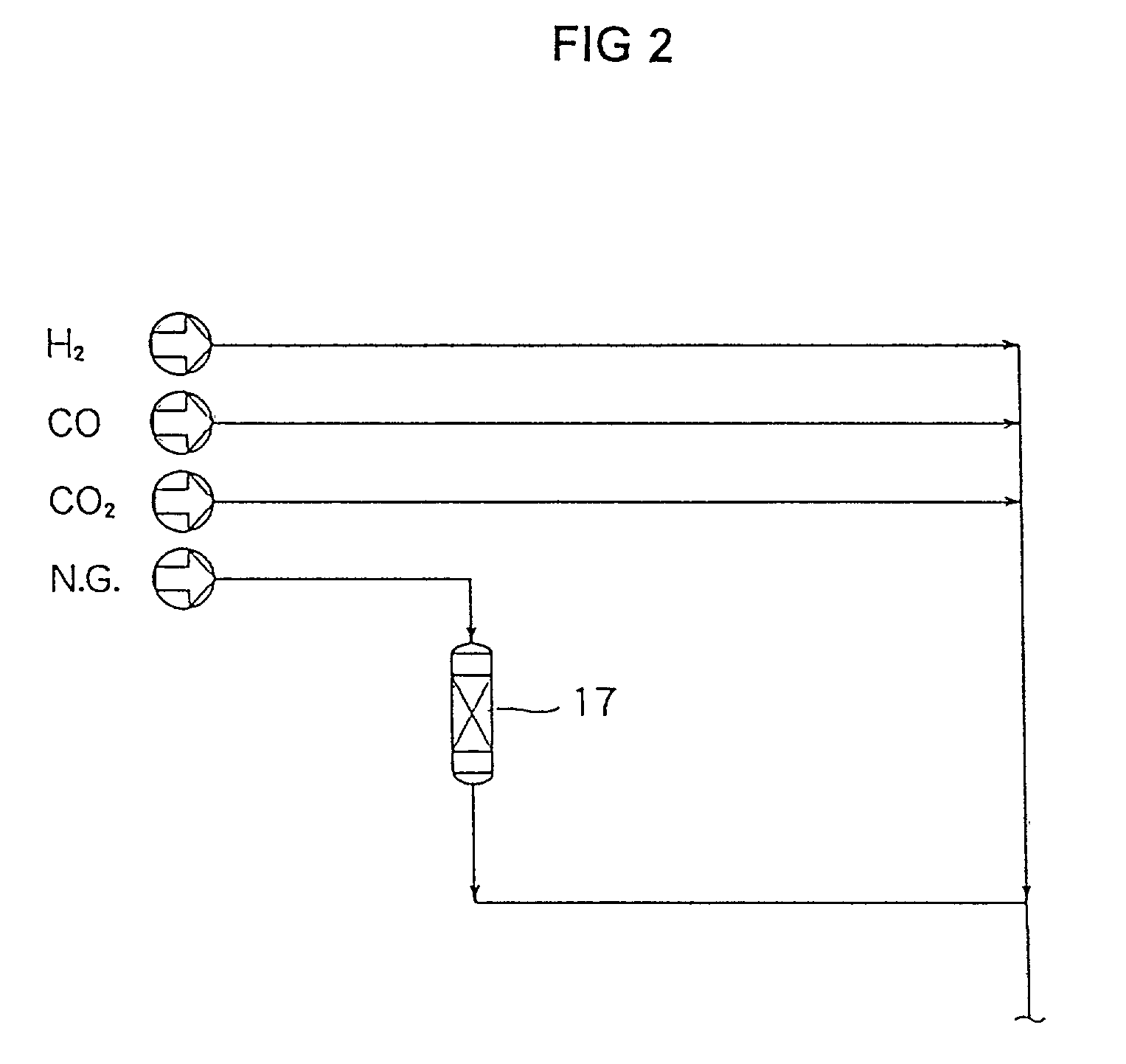
[0079] FIG. 1 is a flow diagram showing the entire construction in case of applying the present invention to an apparatus for producing iron carbide having two reactors (two reactor stages). In FIG. 1, grainy raw materials (iron oxide) are charged into an ore dryer 2 as indicated by arrow 1, and said iron oxide is dried in the ore dryer 2 by high temperature gas introduced from hot gas generator 3, and thereafter, said iron oxide is carried to first fluidized bed reactor 4.

[0080] In first fluidized bed reactor 4, the grainy iron oxide is preliminarily reduced under fluidizing by the reducing gas introduced from the bottom of said reactor. The preliminarily reduced iron oxide is carried to second fluidized bed reactor 5. In second fluidized bed reactor 5, the grainy preliminarily reduced iron oxide is further re...


PUM

PropertyMeasurementUnit
Temperatureaaaaaaaaaa
Pressureaaaaaaaaaa
Flow rateaaaaaaaaaa

Abstract

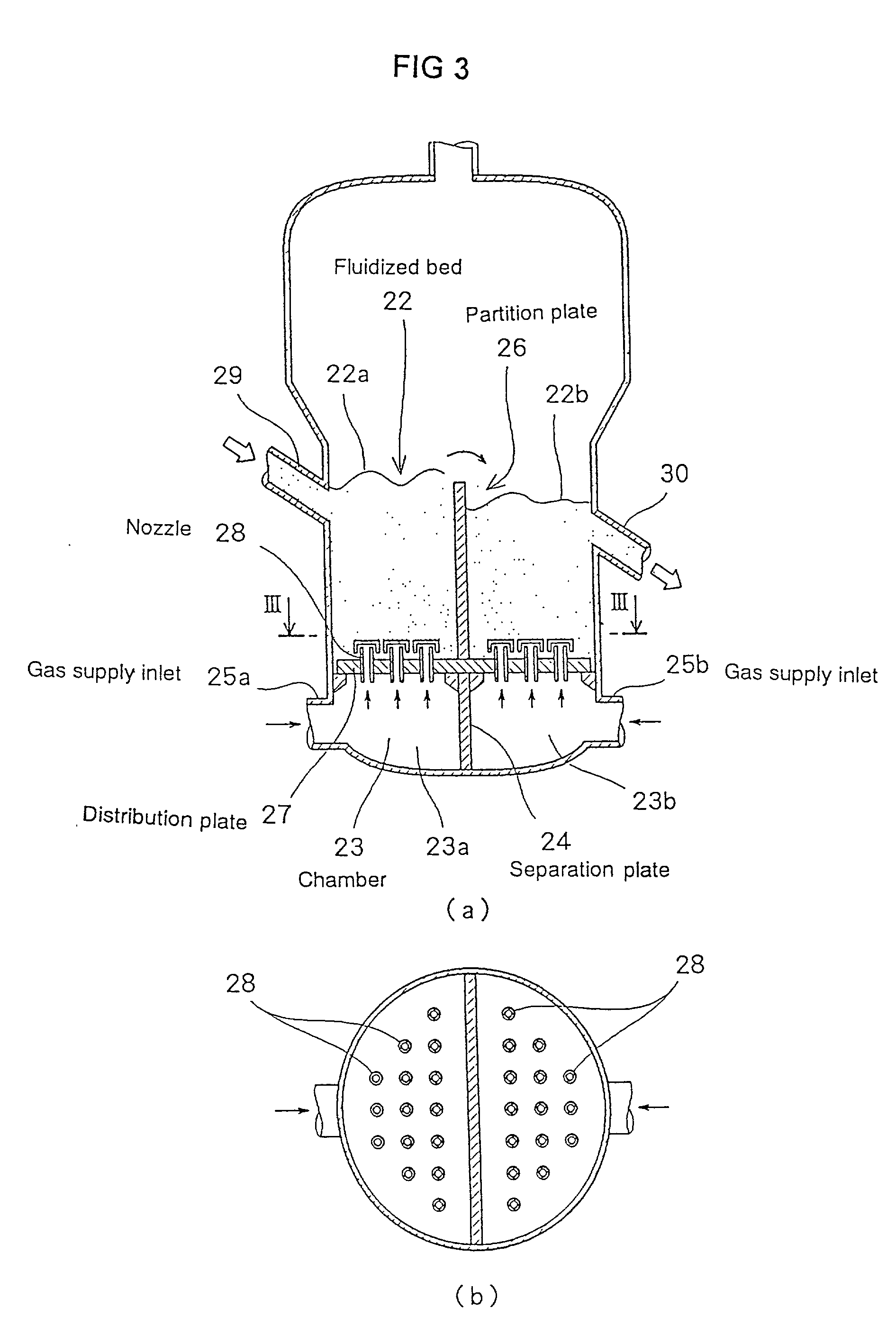
Iron carbide is produced by an apparatus comprising first fludized bed reactor 4 and second fluidized bed reactor 5, wherein the charged grainy iron oxide is reduced and carburized by the high temperature and high pressure gas being introduced from the bottom of the reactor. Both fluidized bed reactors comprise chamber 23 for introducing gas into the reactor, distribution plate 27 having multiple gas-introducing nozzles 28, partition plate 26 partitioning the fulidized bed into plural division rooms, and gas supply inlet 25a, 25b arranged on chamber 23 for supplying gas to specific division room respectively. Each gas supply inlet is connected to gas supply line having a gas flow control valve for controlling gas pressure or gas flow rate. There is provided with a gas circulation loop having a quenching tower 10a,10b and cooler 12a, 12b which eliminate dust contained in the exhaust gas of the reactor, and having a preheater 15a, 15b for heating the gas, wherein the exhaust gas is returned to the chamber by way of quenching tower, cooler and preheater. Using the above apparatus, a grainy iron oxide is reacted with gas and iron carbide is produced by the steps of; charging a grainy iron oxide from a side wall of fluidized bed reactor 4, 5; reducing and carburizing the grainy iron oxide under floating and fluidizing by high temperature and high pressure gas being introduced from the bottom of the reactor; transferring the grainy iron oxide from the division room of the upstream side to the division room of the downstream side via a communication space located at either upper or lower part of the partition plate under fluidizing; discharging produced iron oxide from the final division room.

Description

[0001] The present invention relates to a process and apparatus for producing iron carbide.[0002] A traditional method for producing steel from iron oxide such as iron ore normally comprises the steps of;[0003] in the first step, producing molten pig iron in such a manner that coke produced at a coke oven, other raw materials and iron oxide are charged into a blast furnace, and thereafter, iron oxide are molten and reduced by combustion heat of carbon contained in coke generated due to blowing of high temperature oxygen and carbon monoxide generated due to combustion of said carbon;[0004] in the second step, charging the molten pig iron into a converter, and converting the molten pig iron by oxygen blowing into steel, wherein a carbon concentration of which is under the demanded value.[0005] Since such traditional steel making process by a blast furnace requires many ancillary facilities such as coke oven, sintering furnace, and air-heating furnace, equipment cost becomes high. Furt...

Claims


Application Information

Patent Timeline
IPC IPC(8): B01J8/26B01J8/34B01J8/36B01J8/44C21B13/00
CPCB01J8/26B01J8/34B01J8/36B01J8/44C21B13/0033C21B13/0086Y02P10/134
Inventor NAKATANI, JUNYAUCHIYAMA, YOSHIOINOUE, EIJIMIYASHITA, TORAKATSU
Owner JP STEEL PLANTECH
Learn More