Light-emitting diode device

a diode and light-emitting technology, applied in the field of light-emitting diodes, can solve the problems of insufficient red light in the white, large space and higher costs, and inability to achieve the intended color ton

Inactive Publication Date: 2001-12-13
ASAHI RUBBER
View PDF0 Cites 128 Cited by
  • Summary
  • Abstract
  • Description
  • Claims
  • Application Information

AI Technical Summary

Problems solved by technology

However, using a full-color LED device as a light source causes a complicated design, since each of the light-emitting elements in the full-color LED device requires an anode terminal and a cathode terminal.
Further, a larger space and higher costs are required since a full-color LED device uses three kinds of light-emitting elements.
In addition, if one light-emitting element of a full-color LED device is broken, a desired color balance is lost, with the result that an intended color tone may not be obtained.
Thus, red light is insufficient in the white LED obtained by combining a blue light-emitting element for emitting light having an excitation wavelength of YAG and the YAG phosphor.
This leads to a problem that a matter to be displayed in red looks subdued.
However, such a method cannot provide a white LED device having an average color rendering evaluation number (Ra) of 85 or larger which is an index as to whether an object being illuminated conforms to color perception under a referenc

Method used


Image

  • Light-emitting diode device
  • Light-emitting diode device
  • Light-emitting diode device

Examples


first embodiment

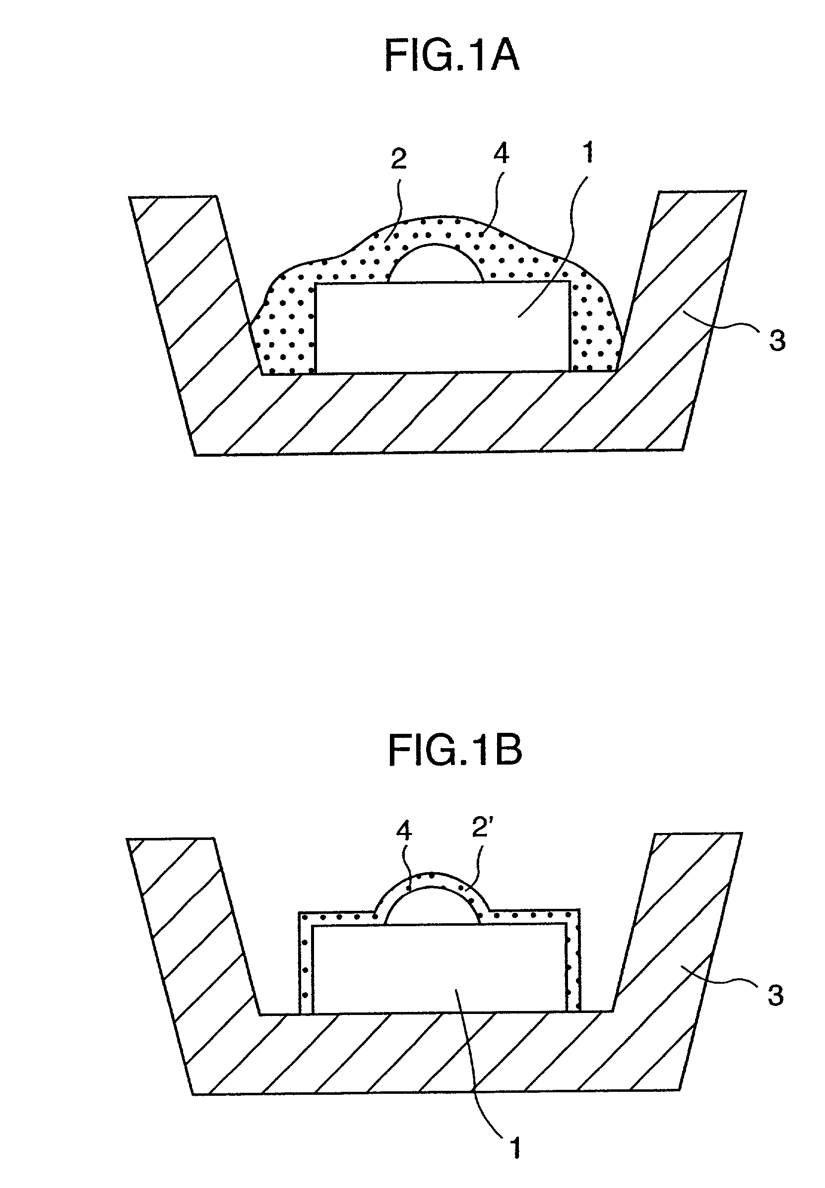
[0048] the LED device according to the invention is such that the fluorescent substance has a form of a layer placed on an outer surface of the light-emitting element. For example, a fluorescent layer 2 may be formed by coating the outer surface of the light-emitting element 1 with a coating agent containing a phosphor 4 as shown in FIG. 1A or a fluorescent layer 2' may be formed by adhering a film made of a resin composition containing the phosphor 4 to the outer surface of the light-emitting element 1 as shown in FIG. 1B. The light-emitting element 1 having the fluorescent layer 2 (or 2') placed thereon may construct a chip-type LED device by being placed in a cup 3 connected with a lead wire (not shown). The chip-type LED device may be sealed with a transparent resin to provide a sealed-type LED device.

[0049] The coating agent used for forming the fluorescent layer contains the above-mentioned red phosphor, the YAG phosphor if necessary, binder and solvent. The fluorescent layer ...

second embodiment

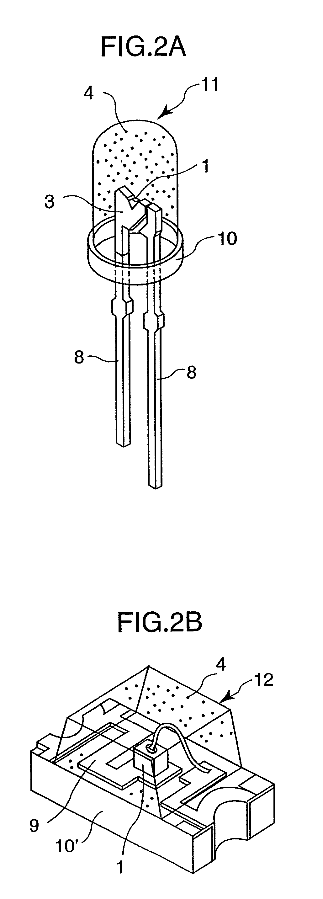
[0050] the LED device according to the invention is a sealed-type LED such that the light-emitting element is embedded and sealed by a resin containing the red phosphor. One example of the LED device having a cannonball-shape is shown in FIG. 2A. The light-emitting element 1 is placed in the cup 3 connected with a lead frame 8. With this assembly set on a substrate 10 through which the lead frame 8 is insertable, a cannonball-shaped sealed-type LED 11 is formed on the substrate 10 by molding a resin composition containing the red phosphor 4 into a cannonball-shape. The sealed-type LED 11 is formed as to embed the light-emitting element 1 in the fluorescent substance. FIG. 2B shows an example of the LED device having a block-shape. With the light-emitting element 1 placed on a lead wire printed on a substrate 10', a block-shaped sealed-type LED 12 is formed by molding a resin composition containing the red phosphor 4 into a block-shape.

[0051] The resin composition used for sealing th...

third embodiment

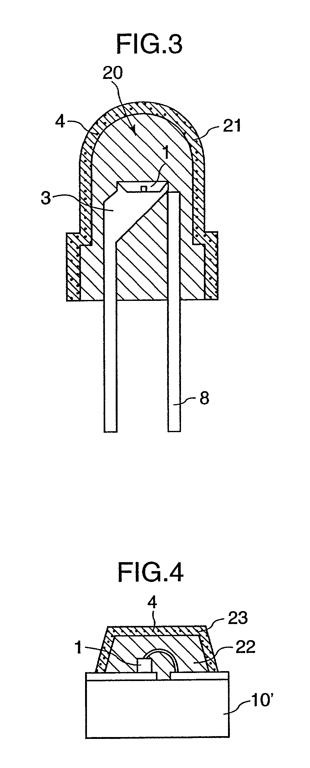
[0055] In the present invention, the light-emitting element is sealed with a transparent resin to form a sealed member, and the sealed member is covered with a covering member including the above-mentioned red phosphor. Specifically, as shown in FIG. 3, a sealed member 20 is formed by sealing the light-emitting element 1 placed in the cup 3 connected with the lead frame 8 and is covered with a covering member 21 containing the phosphor 4. FIG. 4 shows a LED device where the sealed member is block-shaped. A covering member 23 used for covering the block-shaped sealed member 22 is formed so as to conform to the shape of the sealed member 22.

[0056] The shape of the sealed member and a terminal connecting method used in the third embodiment are not particularly limited. For example, as shown in FIG. 5, a sealed member 20' having a projecting locking portion 24 may be used, thereby accomplishing a stable mounting a covering member 21' to the sealed member 20'. The covering member 21' inc...


PUM


Abstract

A LED device which has an excellent color rendering property and no toxicity and does not bring about an increase in production cost more than necessary, and a covering member used for such a LED device can be provided. The white LED device comprises a light-emitting element for emitting light of blue to green region and a fluorescent substance containing a red phosphor for converting a wavelength of the light emitted from the light-emitting element. The red phosphor is CaS or activated by Eu or a phosphor expressed by a general formula AEu(1-x)LnxB2O8 wherein A is an element selected from the group consisting of Li, K, Na and Ag; Ln is an element selected from the group consisting of Y, La and Gd; and B is W or Mo; and x is number equal to or larger than 0, but smaller than 1.

Description

[0001] The present invention relates to a white light-emitting diode device having an excellent color rendering property which is used in a back light and a front light as an externally irradiating light source of a color liquid crystal display and used for room illumination and, particularly to a covering member enabling a conventional blue or green light-emitting diode device to emit white light, and a white light-emitting diode device using the covering member.DESCRIPTION OF THE RELATED ART[0002] A light-emitting diode (hereinafter, referred to as "LED") emits a light when electrons from an N-region and holes from a P-region are moved to a PN junction section and recoupled in a PN junction semiconductor when a forward voltage is applied. Since energies released when the free electrons are coupled are radiated as light, the light emitted from the LED is light in a narrow wavelength range, i.e. light of a single color such as red and blue.[0003] On the other hand, a light source fo...

Claims


Application Information

Patent Timeline
IPC IPC(8): G02F1/1335G02F1/13357H01L33/32H01L33/50H01L33/52
CPCC09K11/7731C09K11/7774C09K11/7794H01L33/502H01L33/62H01L2224/48091H01L2224/48247H01L2924/00012H01L2924/00014
Inventor ODAKI, TSUTOMUTASAKI, MASUTSUGUICHIKAWA, AKIRATAKAGI, KAZUHISAHASHIMOTO, KAZUAKI
Owner ASAHI RUBBER
Why Eureka
Try Eureka