Corrugated plastic pipe sections having flanged ends and structurally tight joints thereof

a corrugated plastic pipe and end fitting technology, which is applied in the direction of flanged joints, fluid pressure sealing joints, sleeves/socket joints, etc., can solve the problems of reducing the stress crack resistance of plastic pipes, twisting and rolling, and slipping of corrugated ends, etc., to achieve cost-effective and simplify the in-plant fabrication of flanged end fittings

Inactive Publication Date: 2001-12-27
STARITA JOSEPH M
View PDF0 Cites 21 Cited by
  • Summary
  • Abstract
  • Description
  • Claims
  • Application Information

AI Technical Summary

Benefits of technology

0010] The enhanced joint design and method of fabricating soil tight and water tight joints disclosed is cost effective, allows field cuts of corrugated plastic pipe, and simplifies in-plant fabrication of flanged end fittings from sections of corrugated pipe. A clamp is u

Problems solved by technology

The motion of pushing the gasket on the spigot in an axial direction and the frictional force on the interior lateral surface of the bell may cause the gasket to un-seat, twist and roll.
In addition, circumferential tensile stresses on the interior of the bell, required to maintain gasket compression, decrease the stress crack resistance of the plastic pipe.
In the prior case the stiffness of the corrugation is not sufficient to withstand the hydrostatic water pressure required to prevent water leaks.
Both solutions add considerable cost obtain a reliable water tight joint.
A further disadvantage of joints that utilize radial compressed gaskets is that the joints are subject to failure, leaking water under pressure, as a result of rolling and twisting of the gasket or by stress cracking of the bell.
However, the gasket transfers stress to the plastic inner wall or liner and to the corrugations.
Both the corrugations and the liner are relatively low in stiffness and have difficulty maintaining the radial compression of the gasket.

Method used


Image

  • Corrugated plastic pipe sections having flanged ends and structurally tight joints thereof
  • Corrugated plastic pipe sections having flanged ends and structurally tight joints thereof
  • Corrugated plastic pipe sections having flanged ends and structurally tight joints thereof

Examples


example i

[0068] An example of the preferred embodiment is the forming of water tight joints with High Density Polyethylene (HDPE) pipe utilized for drainage and sanitary sewer applications. The circular flange clamp is a "V" retaining coupling fabricated from 301 Stainless Steel and the gasket is extruded and spliced from natural rubber, polyisobutylene or neoprene rubber. In this example, the corrugated HDPE pipe has corrugations that are too flexible to maintain the gasket compression required for water tight sealing. As a result, typically, the corrugations are filled with rigid foam to provide sufficient stiffness. The process of foaming the corrugations is time consuming and relatively expensive. The present invention eliminates stiffening requirements because the rigid clamp provides the stiffness. In this preferred embodiment the wedged shaped gasket may be a cured natural rubber or polyisobutylene having a durometer or hardness on the Shore A scale between 50 and 60. However, a varie...

example ii

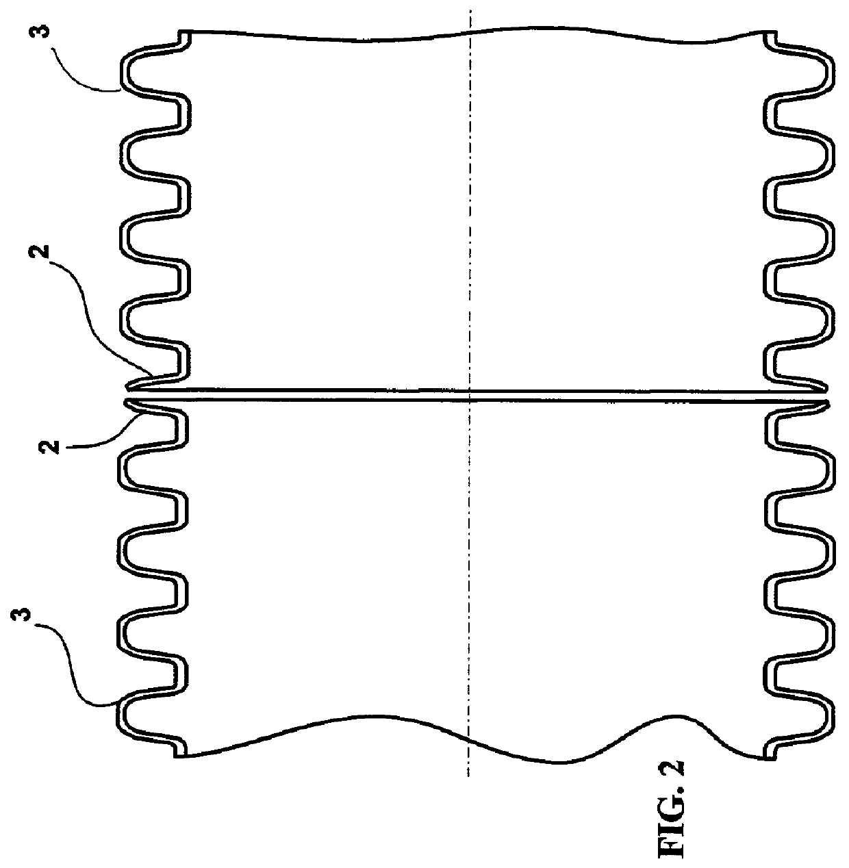
[0070] In this second example, the method and design of soil-tight and water tight joining of single wall corrugated plastic pipe is demonstrated for a second time. FIG. 11A shows two sections of single wall corrugated plastic pipe 3 with a flange 2 formed by a circumferential portion of an end corrugation. FIG. 11B shows the components for fabricating a water tight joint; the single wall plastic pipe 3 with flange 2, the flat gasket 5 and the circular flange clamp 6 in the open position. FIG. 11C shows the assembled joint wherein the circular flange clamp 6 is closed causing the gasket 5 to compress. Flange 2 is in compression avoiding tensile stresses that enhance stress cracking.

example iii

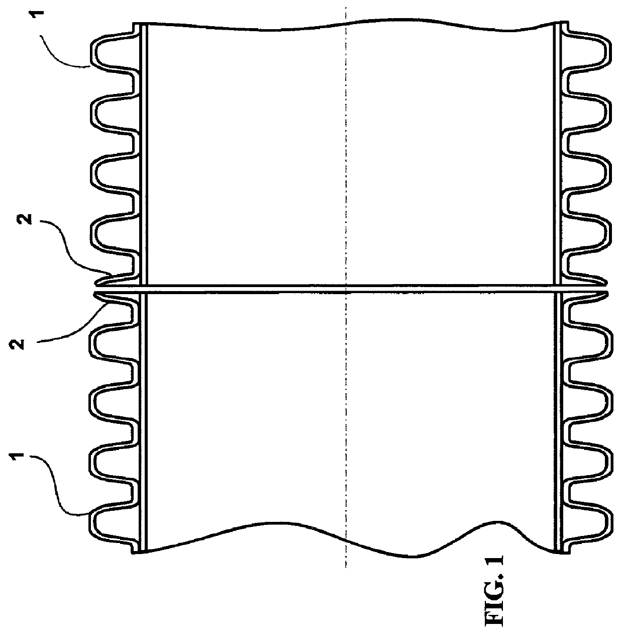
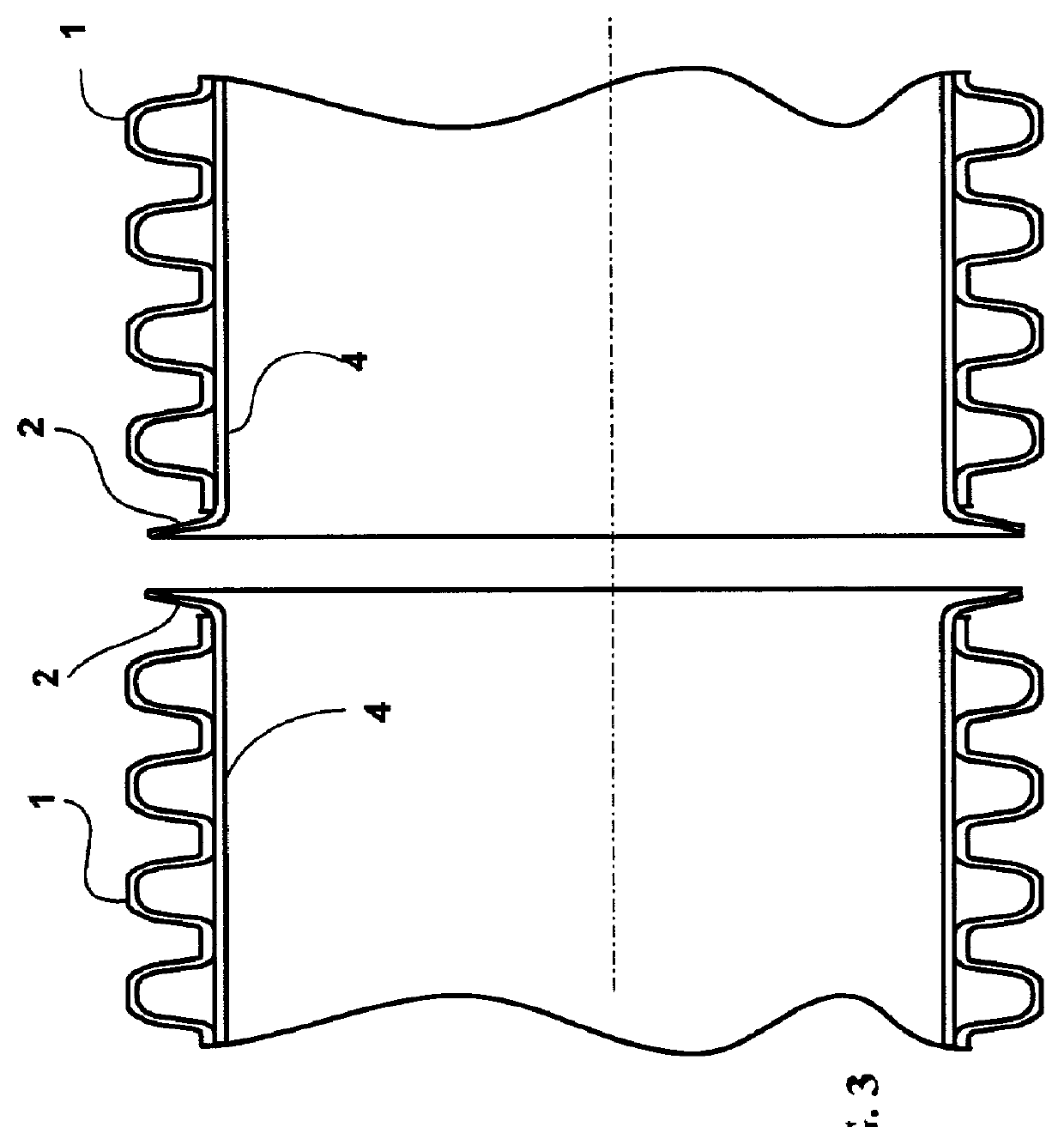
[0071] This example shows an alternate means of applying the disclosed invention to the water tight joining of dual wall corrugated plastic pipe. FIG. 2A shows two sections of dual wall plastic pipe 1 having transverse corrugations and flanges 2 at the pipe end formed from the liner. FIG. 12B shows the components for fabricating a water tight joint; the dual wall plastic pipe 1 with flange 2 formed from the liner 4, the flat gasket 5 and the circular flange clamp 6 in the open position. FIG. 12C shows the assembled joint wherein the circular flange clamp 9 is closed causing the gasket 5 to compress.


PUM


Abstract

Corrugated plastic pipe sections having a flanged end formed by a circumferential portion of an end corrugation or section of the pipe liner and a method and kit for joining flanged end corrugated plastic pipe sections are described in a system in which a portion of the end corrugation or pipe liner forms a flange and a peripheral flange clamp straddles flanges and draws the flanges together to provide a structurally sound joint. A gasket may be interposed between flanges or the flange periphery and the clamp. The invention achieves a cost effective tight joint, allows field cuts of the corrugated plastic pipe and the fabrication of fittings from corrugated pipe sections and provides a selectable pipe size reducer coupling for corrugated plastic pipe.

Description

CROSS-REFERENCE TO RELATED APPLICATIONS[0001] This application is a continuation-in-part of my co-pending applications "Joint and Seal for Large Diameter Corrugated Plastic Pipe and Method for Joining Plastic Pipe Sections," Ser. No. 09 / 597,338 filed on Jun. 19, 2000; "Water tight Joint and Method of Sealing Drainage and Sanitary Sewer Pipe Sections," Ser. No. 09 / 788,913 filed on Feb. 19, 2001; and "Method and Joint Design for Infield Water Tight Sealing of Dual Wall Corrugated Plastic Pipe Sections," Ser. No. 09 / 794,638 filed on Feb. 27, 2001.BACKGROUND OF THE INVENTION[0002] Large diameter corrugated plastic (typically formed from polyethylene) pipe sections are known products. Past and present attempts to design water tight joints for corrugated plastic pipe to expand the use of the pipe to drainage and sanitary sewer applications typically involve radial compression of a gasket (molded or extruded and spliced) that occurs when an end section of the pipe formed as a spigot is ins...

Claims


Application Information

Patent Timeline
IPC IPC(8): F16L9/06F16L9/18F16L21/03F16L23/036F16L23/06F16L23/08F16L25/00
CPCF16L9/06F16L9/18F16L21/03F16L23/036F16L23/06F16L23/08F16L25/0045F16L25/0054F16L25/0063Y10S285/903
Inventor STARITA, JOSEPH M.
Owner STARITA JOSEPH M
Why Eureka
Try Eureka