Antenna with a conductive layer and a two-band transmitter including the antenna

a technology of conductive layer and antenna, which is applied in the direction of resonant antennas, substantially flat resonant elements, antenna earthings, etc., can solve the problems of high cost, difficult, and therefore expensive, to obtain the required resonant frequencies, and complex fabrication of antennas

Inactive Publication Date: 2002-01-10
ALCATEL LUCENT SAS
View PDF0 Cites 197 Cited by
  • Summary
  • Abstract
  • Description
  • Claims
  • Application Information

AI Technical Summary

Benefits of technology

[0034] providing a simple way of producing a two-frequency antenna with a coupling system whose impedance is easy to match at each of two resonant frequencies, and

Problems solved by technology

The above antenna has the particular disadvantage that its fabrication is complicated by the incorporation of point short circuits.
They then have the particular drawback that the cumulative thickness of the dielectric substrates between the layers makes the total thickness of the antenna excessive.
As a general rule, the above prior art antennas have the drawback that it is difficult, and therefore costly, to obtain the required resonant frequencies at the same time as good coupling of each resonance to a signal processor.

Method used


Image

  • Antenna with a conductive layer and a two-band transmitter including the antenna
  • Antenna with a conductive layer and a two-band transmitter including the antenna
  • Antenna with a conductive layer and a two-band transmitter including the antenna

Examples


first embodiment

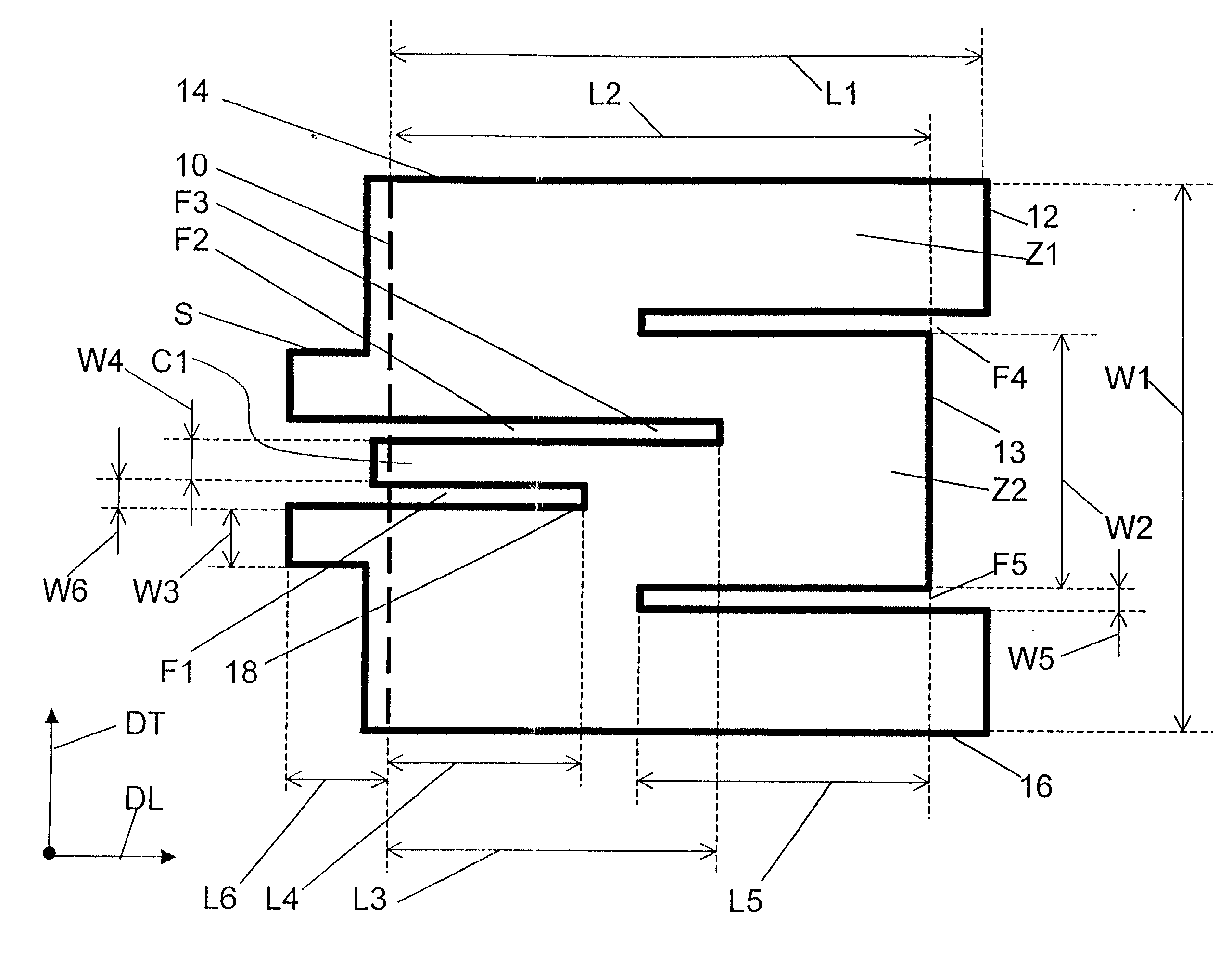
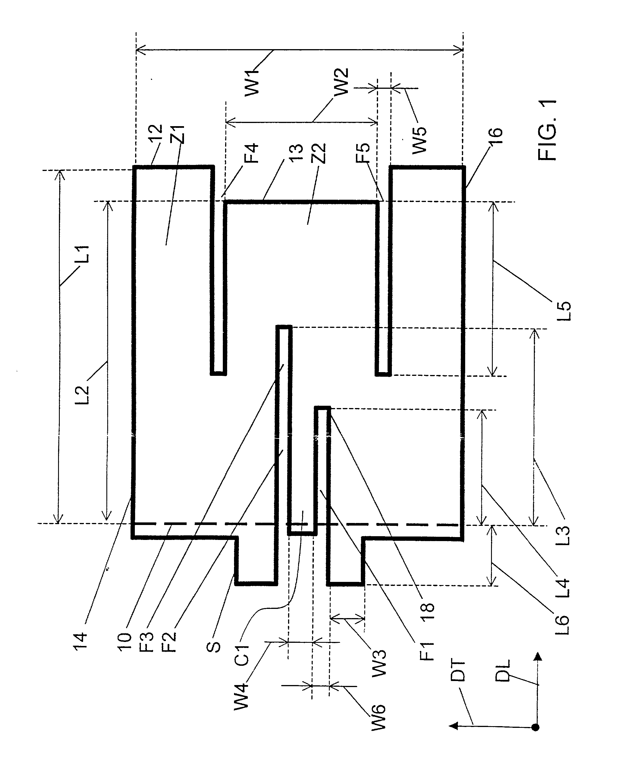
[0059] In the invention, the separator system includes two separator slots F4 and F5 in the patch 6 extending in the longitudinal direction DL from the front edge 12 of the patch, so that two lateral edges of the secondary resonance area Z2 consist of respective edges of the two slots and a front edge of the area consists of a segment 13 of the front edge between the two slots.

[0060] As shown in FIG. 1, a copper sheet constituting the patch 6 has an extension toward the front beyond a line that is intended to constitute the rear edge 10 of the patch. During fabrication of the antenna it is bent about this line along the rear edge of the substrate so that the extension is pressed onto the vertical edge of the substrate. Part of the extension is connected to the substrate to constitute the short circuit S. The short circuit is in a middle segment of this edge and is in two parts on respective opposite sides of the coupling system C1, F1, F2. The other parts of the extension are not sh...

second embodiment

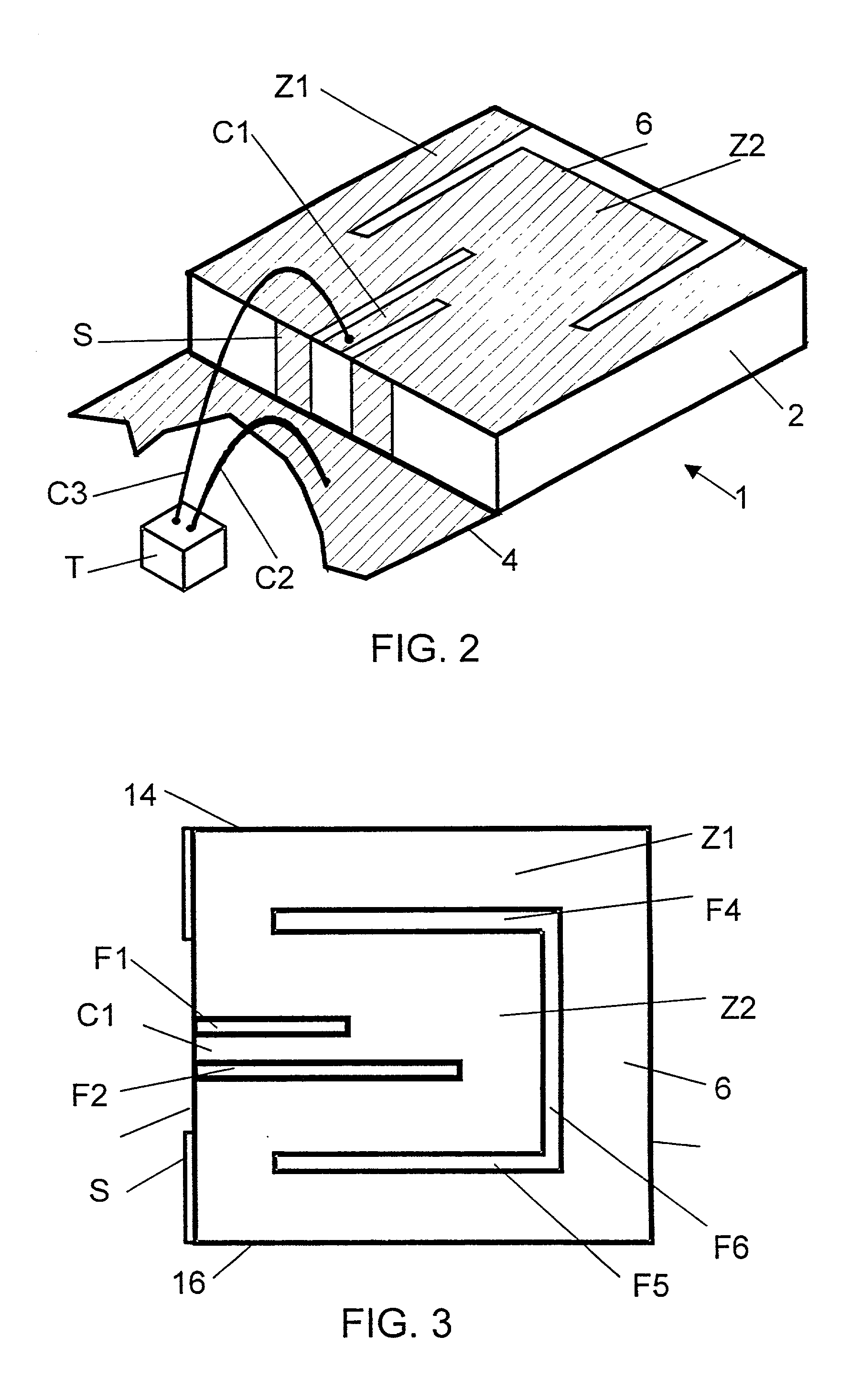
[0081] In the invention, shown in FIG. 3, the separator system includes a U-shaped separator slot at a distance from the edges of the patch 6. The slot has two branches F4 and F5 connected together by a base F6. The two branches extend in the longitudinal direction, facing and spaced from the lateral edges 14 and 16, respectively, and the base extends in the transverse direction, facing and spaced from the front edge 12.

[0082] It is assumed that these two embodiments of the antenna operate in the following manner.

[0083] The coupling between firstly the standing wave of each of the two primary and secondary resonances and secondly the waves radiated in space occurs principally at one or more edges of the patch 6 or the separator slots F4, F5 and F6, or through the slots. This kind of edge or slot could therefore be called a primary or secondary radiating edge or slot, depending on the resonance concerned.

[0084] In both embodiments of the invention there is a single primary radiating ...


PUM


Abstract

The antenna of said transmitter is a microstrip antenna. A rear edge of its patch is provided with a short circuit by means of which a quarter-wave primary resonance can be excited by a coplanar line formed by two coupling slots in an area. Separator slots separate said area from another area in which a secondary resonance can be established at twice the frequency of the primary resonance from a slotted line extending one slot of the coplanar line. The invention applies in particular to the production of a dual-mode mobile telephone to the GSM and DCS standards.

Description

[0001] The present invention relates generally to radio transmitters, in particular mobile telephones, and more particularly to antennas for inclusion in such transmitters and including a conductive layer.[0002] This kind of antenna includes a patch which is typically obtained by etching a metal layer. It is then called a microstrip patch antenna.[0003] The microstrip technique is a planar technique that is used to make transmission lines for transmitting guided waves, possibly carrying signals, and antennas coupling such lines and radiated waves. It uses conductive patches and / or strips formed on the top surface of a thin dielectric substrate. A conductive layer extends over the bottom surface of the substrate and constitutes an earth layer of the line or the antenna. The patch is typically wider than the strip and its shape and dimensions are important characteristics of the antenna. The substrate is typically a plane rectangular sheet of constant thickness and the patch is also t...

Claims


Application Information

Patent Timeline
Patent Type & Authority Applications(United States)
IPC IPC(8): H01Q13/08H01Q1/24H01Q1/38H01Q5/00H01Q5/10H01Q5/371H01Q9/04
CPCH01Q1/243H01Q5/371H01Q9/045H01Q9/0421
Inventor KOUAM, CHARLES NGOUNOUCOUPEZ, JEAN-PHILIPPE
Owner ALCATEL LUCENT SAS
Why Eureka
Try Eureka