Backlight for color liquid crystal, color liquid crystal display device, and EL element for backlight of color liquid crystal device

a color liquid crystal display device and backlight technology, which is applied in the direction of instruments, discharge tube luminescnet screens, static indicating devices, etc., can solve the problems of large installation space, large power consumption, and inability to be used as the display portion of portable information terminals such as pda's and portable telephones

Inactive Publication Date: 2002-01-10
KK TOSHIBA
View PDF0 Cites 23 Cited by
  • Summary
  • Abstract
  • Description
  • Claims
  • Application Information

AI Technical Summary

Problems solved by technology

However, the cold-cathode tube, in addition to being large in power consumption, requires a large space for installation.
As a result, it cannot be employed as the display portion of the portable information terminals such as PDA's and portable telephones.
That is, for the display portion that requires smaller and thinner size and lower power consumption, a color liquid crystal display device having a backlight consisting of a cold-cathode tube cannot be applied.
However, the LED, being a point light source, has disadvantages such as the tendency to cause unevenness or light leakage when displaying in a larger screen, or breakage under high load operation.
Furthermore, when the LED is used as the backlight, a plurality of LED's are necessary according to a dimension of a display screen, a rise of the device cost being inevitably caused.
However, the copper activated zinc sulfide phosphor can emit only in from blue green to green color, resulting in inferior color reproducibility.
Furthermore, the EL element is insufficient in brightness in comparison with the LED.
However, the existing EL element is insufficient in white light reproducibility and brightness, as a result the EL element has never been put into practical use as the backlight of the color liquid display device.
Furthermore, on the basis of the difference of the configuration of the EL light-emitting layer or the like, a backlight disclosed in the above gazette cannot give white light of sufficient brightness.
However, when the copper activated zinc sulfide phosphor emitting in blue green or in blue and the red fluorescent pigment are simply concurrently used, there is the great risk that the brightness of the white light becomes insufficient.
The reason why the existing EL element was not put into practical use as the backlight of the color liquid crystal display device is primarily due to a fact that in the existing EL element the white light of high brightness cannot be obtained with good reproducibility.
However, the red fluorescent pigment, when added excessively, tends to cause deterioration of the emission brightness.
The aforementioned red fluorescent pigment is inferior in the luminous efficiency to the copper activated zinc sulfide phosphor.
While on the other hand the desired white light can be obtained, there is the risk of deteriorating the brightness as the EL element 10.
When the average thickness of the moisture-proof film is less than 0.1 .mu.m, there is the risk of not obtaining sufficient moisture-proof effect.
On the other hand, when the average thickness of the moisture-proof film exceeds 1.0 .mu.m, not withstanding an essentially transparent moisture-proof film, there is the risk of deteriorating the emission brightness due to light absorption such as reflection and refraction.
However, in addition to raising the manufacturing cost, a thickness of the EL element 10 itself also becomes thicker.

Method used


Image

  • Backlight for color liquid crystal, color liquid crystal display device, and EL element for backlight of color liquid crystal device
  • Backlight for color liquid crystal, color liquid crystal display device, and EL element for backlight of color liquid crystal device
  • Backlight for color liquid crystal, color liquid crystal display device, and EL element for backlight of color liquid crystal device

Examples


embodiment 2

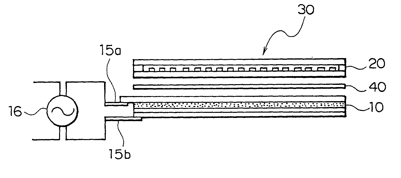
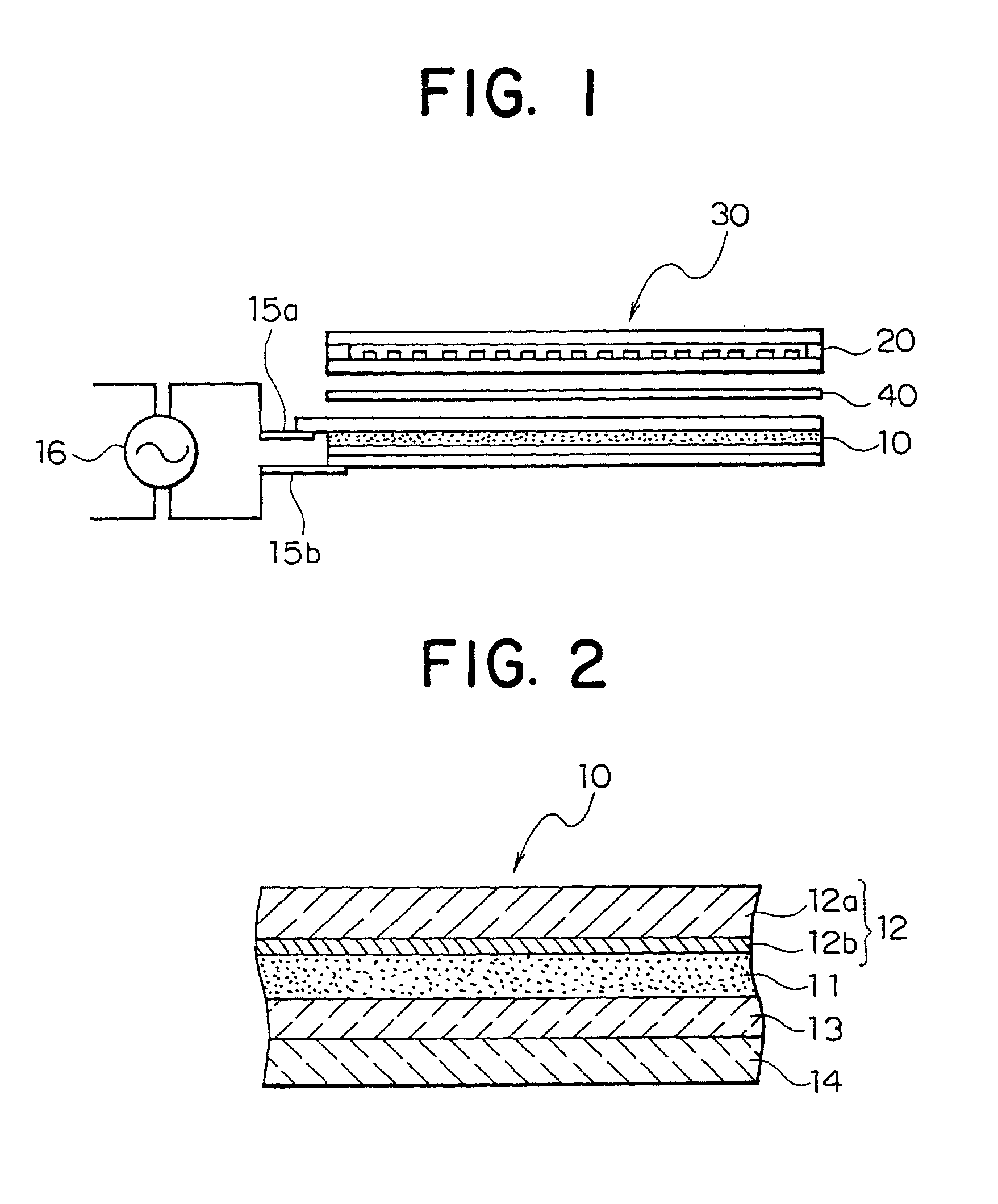
[0070] First, 99.5 mass percent of the same blue green emitting ZnS: Cu phosphor powder with Embodiment 1 and 0.5 mass percent of rhodamine group fluorescent pigment, a red fluorescent pigment, are mixed. The above mixture is dispersed in fluororubber together with an appropriate amount of organic solvent to prepare slurry. Then, on a transparent electrode film that is formed by depositing an ITO film on a polyester film, the aforementioned phosphor slurry is screen-printed to form a light-emitting layer of a thickness of 50 .mu.m.

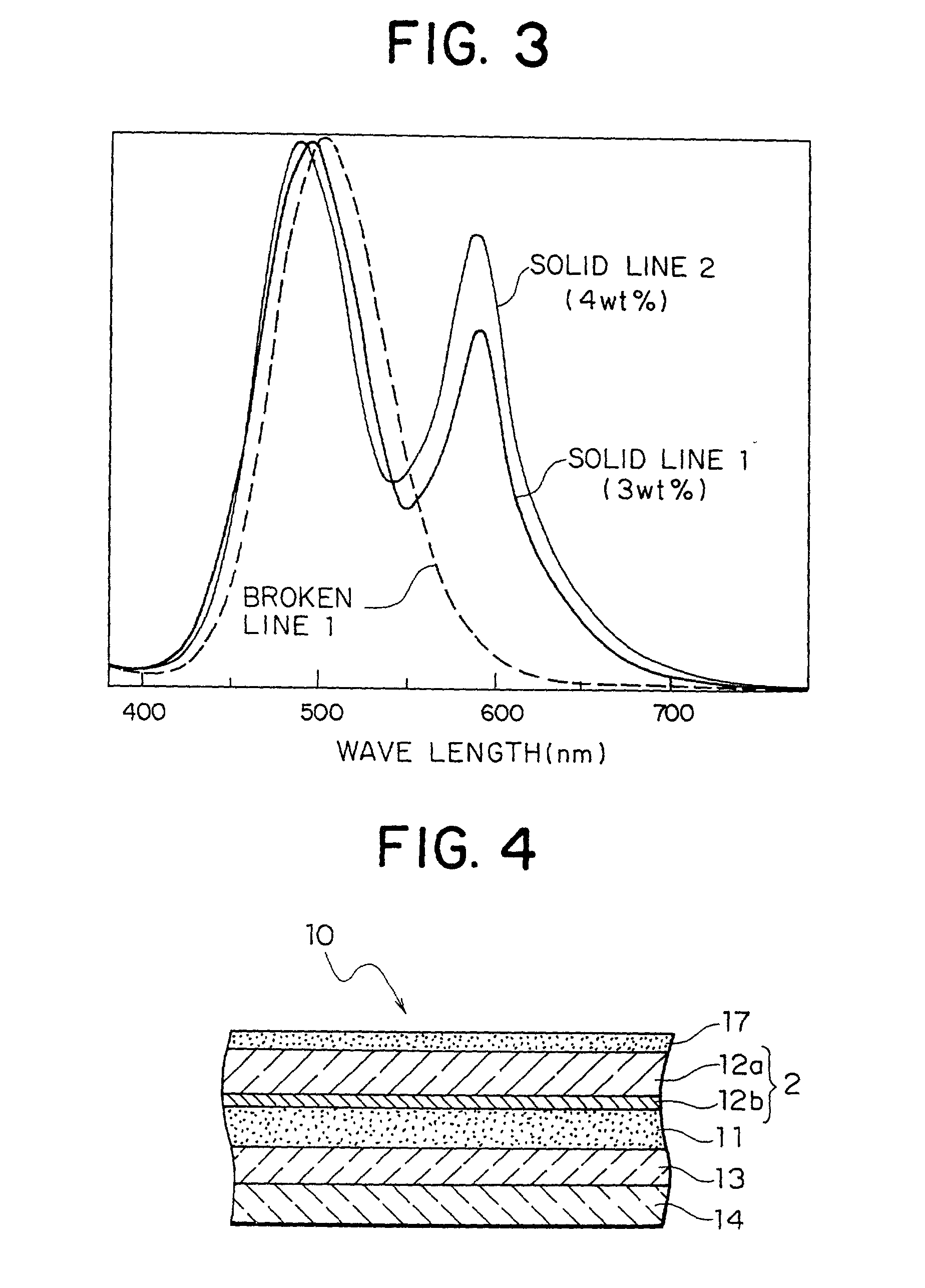
[0071] Next, on the aforementioned light-emitting layer, by the use of an ordinary method, a reflective insulating layer and a rear electrode layer are stacked in turn. Thereafter, a fluorescent pigment layer containing 3 mass percent of rhodamine group fluorescent pigment with respect to the phosphor powder of the light-emitting layer is printed on the transparent electrode layer to form a color filter layer. Thus obtained bare EL element has a luminous e...

embodiment 3

[0072] First, 99 mass percent of blue emitting ZnS: Cu phosphor powder with moisture-proof film consisting of alumina film and 1 mass percent of rhodamine group fluorescent pigment, a red fluorescent pigment, are mixed. The above mixture is dispersed in fluororubber together with an appropriate amount of organic solvent to prepare slurry. Then, on a transparent electrode film that is formed by depositing an ITO film on a polyester film, the aforementioned phosphor slurry is screen-printed to form a light-emitting layer of a thickness of 50 .mu.m.

[0073] The ZnS: Cu phosphor used here contains 0.05 mass percent of Cu with respect to ZnS, and has, under the operational conditions of a voltage of 100 Vrms and a frequency of 400 Hz, emission brightness of 102 cd / m.sup.2 and chromaticity of (0.179, 0.35) by the CIE chromaticity coordinate. The brightness and chromaticity of the ZnS: Cu phosphor are measured based on the aforementioned method.

[0074] Next, on the aforementioned light-emitti...

embodiment 4

[0075] 49.5 mass percent of the same blue green emitting ZnS: Cu phosphor powder with Embodiment 1, 49 mass percent of the same blue emitting ZnS: Cu phosphor powder with Embodiment 3 and 1.5 mass percent of rhodamine group fluorescent pigment, a red fluorescent pigment, are mixed. The above mixture is dispersed in fluororubber together with an appropriate amount of organic solvent to prepare slurry. Then, on a transparent electrode film that is formed by depositing an ITO film on a polyester film, the aforementioned phosphor slurry is screen-printed to form a light-emitting layer of a thickness of 50 .mu.m.

[0076] Next, on the aforementioned light-emitting layer, according to an ordinary method, a reflective insulating layer and a rear electrode layer are stacked in turn. Thereafter, a fluorescent pigment layer containing 5 mass percent of rhodamine group fluorescent pigment with respect to the phosphor powder of the light-emitting layer is printed on the transparent electrode layer...


PUM

PropertyMeasurementUnit
brightnessaaaaaaaaaa
frequencyaaaaaaaaaa
brightnessaaaaaaaaaa

Abstract

A backlight for color liquid crystal comprises a light-emitting layer having EL phosphor particles dispersed in a matrix of dielectrics, a transparent electrode layer disposed along a main surface on an emitting side of a light-emitting layer, and a reflective insulating layer and a rear electrode layer stacked in turn along a main surface on a non-emitting side of a light-emitting layer. An EL element, under the operational conditions of a voltage of 100 Vrms and a frequency of 400 Hz, emits white light of which brightness is 80 cd/m2 or more, and has characteristics of consumption power of 30 W/m2 or less. By the use of such EL element as a backlight, a color liquid crystal display device that is low in consumption power, excellent in display performance and suitable for a display portion of a portable information terminal can be provided.

Description

[0001] 1. Field of the Invention[0002] The present invention relates to a backlight for a color liquid crystal display device, a color liquid crystal display device, and an EL element for a backlight of a color liquid crystal display device.[0003] 2. Description of the Related Art[0004] Color liquid crystal display devices are used as display devices for computers, game machines and various kinds of home appliances. With the recent increase of various kinds of portable information terminals, a large number of liquid crystal display devices are used as display devices for the information terminals. In particular, also in PDA's (personal digital assistants) and portable telephones, color display has been forwarded. Accordingly, demands are strong for color liquid crystal display devices smaller and thinner in size, and lower in power consumption.[0005] The liquid crystal display device, being a display device that does not emit light, is ordinarily provided with a backlight as a light...

Claims


Application Information

Patent Timeline
Patent Type & Authority Applications(United States)
IPC IPC(8): G02F1/13357
CPCG02F1/133603
Inventor ISHII, TSUTOMUNAKAMURA, MITSUOINOUE, KIYOSHI
Owner KK TOSHIBA
Why Eureka
Try Eureka