
Eureka
For R&D, Eureka makes reading and utilizing patents & technical documents easy.
Eureka AIR
Designed for self-driven R&D workflows. Generate viable solutions, solve complex R&D challenges, empower your innovation with AI.

Eureka Materials
Designed for material experts only. Revolutionize your material R&D, from search, analyze, to developing new materials.

TechResearch
Generate reliable direction feasibility study reports for your R&D in just a few steps.

TechSeek
Discover and master advanced knowledge NOW. Basics, ideas, possibilities, all at once.

TechMind
As an expert in R&D Theories, TechMind can generates customized viable solutions instantly.

TechRisk
Analyze your overall solution with one click, know your potential R&D risks in advance.

TechMonitor
Get weekly tech updates, stay abreast of the latest tech innovations and key insights.
Optical fiber amplifier and dispersion compensating fiber module for optical fiber amplifier
- Summary
- Abstract
- Description
- Claims
- Application Information
AI Technical Summary
Benefits of technology
Problems solved by technology
Method used
Image

Examples
first embodiment
[0271] B1. First Embodiment
[0272] Referring now to FIG. 16, there is shown in block diagram an optical fiber amplifier according to a first preferred embodiment of the present invention. The optical fiber amplifier shown includes a pair of erbium-doped-fibers (EDF) 11-1 and 11-2 each as a rare earth doped fiber, a pair of pump sources 12-1 and 12-2, four optical demultiplexer-multiplexers (WDM; optical wave separator-combiners) 13-1 to 13-4 serving as first to fourth optical couplers, respectively, a reflecting mirror (reflection element) 14, an optical circulator 15, three isolators (ISO) 16-1 to 16-3, and an optical filter 17.
[0273] In particular, in the optical fiber amplifier, the isolator 16-1, optical demultilexer-multiplexer 131, erbium-doped-fiber 11-1, optical demultiplexer-multiplexer 13-2, optical filter 17, isolator 16-2, optical demultiplexer-multiplexer 13-3, erbium-doped-fiber 11-2, optical demultiplexer-multiplexer 13-4 and isolator 16-3 are arranged in this order fr...
second embodiment
[0326] B2. Second Embodiment
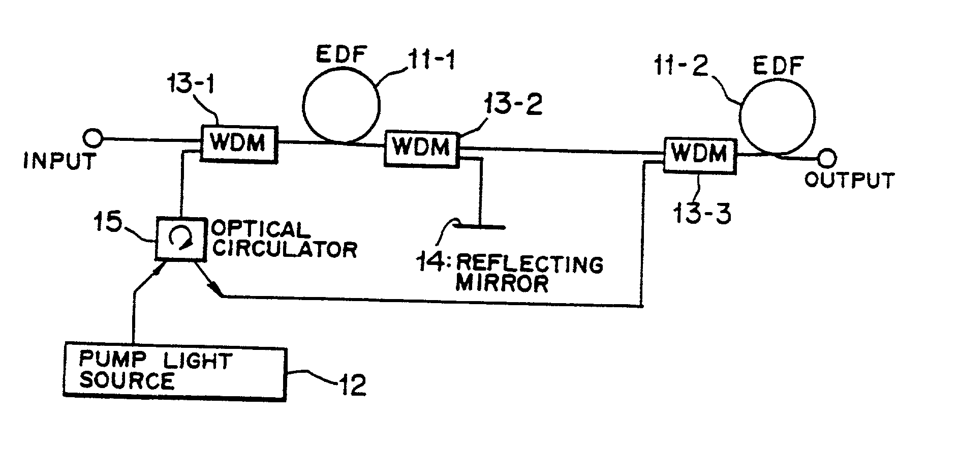
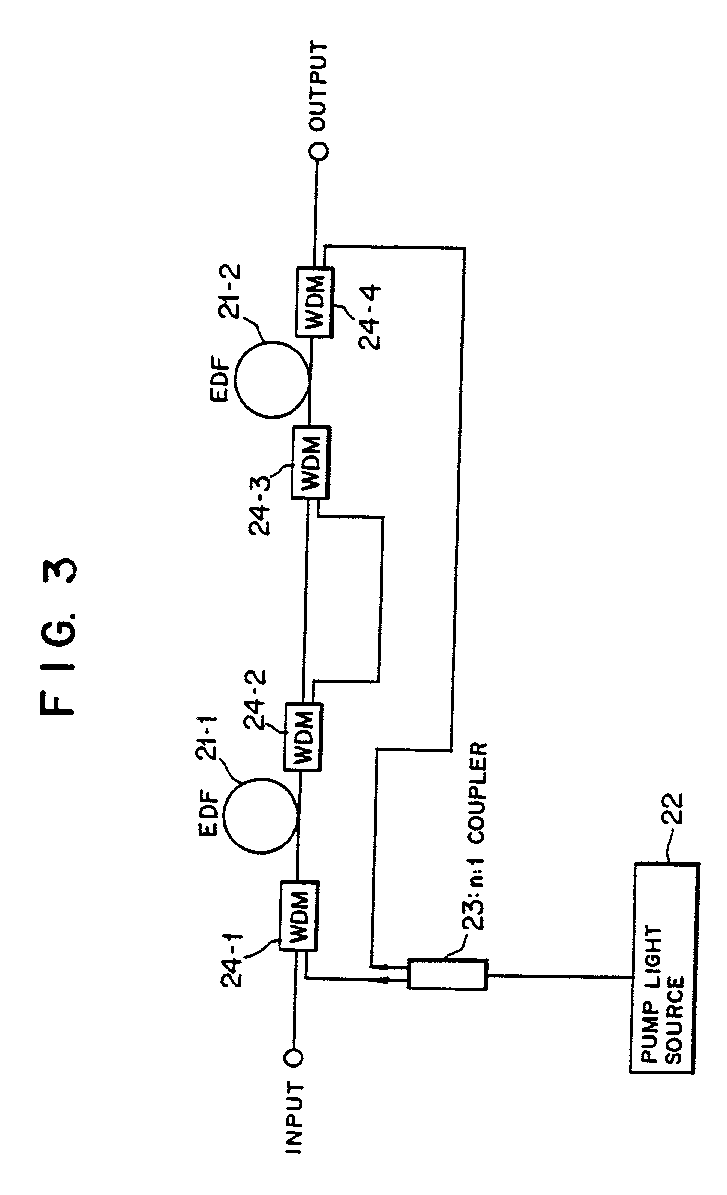
[0327] FIG. 23 is a block diagram showing a second preferred embodiment of the present invention. Referring to FIG. 23, the optical fiber amplifier shown includes an isolator 25-1, an optical demultiplexer-multiplexer (first coupler) 24-1, an erbium-doped-fiber (rare earth doped fiber) 21-1, another optical demultiplexer-multiplexer (second coupler) 24-2, an optical filter 26, another isolator 25-3, a further optical demultiplexer-multiplexer (third coupler) 24-3, another erbium-doped-fiber (rare earth doped fiber) 21-2, a still further optical demultiplexer-multiplexer (fourth coupler) 24-4 and a further isolator 25-4 disposed in this order from the input side.
[0328] An optical signal line including the optical filter 26 and the isolator 25-3 and a pump light line are provided in parallel between the optical demultiplexer-multiplexers 24-2 and 24-3.
[0329] A pump source 22 is connected to the optical demultiplexer-multiplexer 24-1 by way of an optical bra...
third embodiment
[0347] B3. Third Embodiment
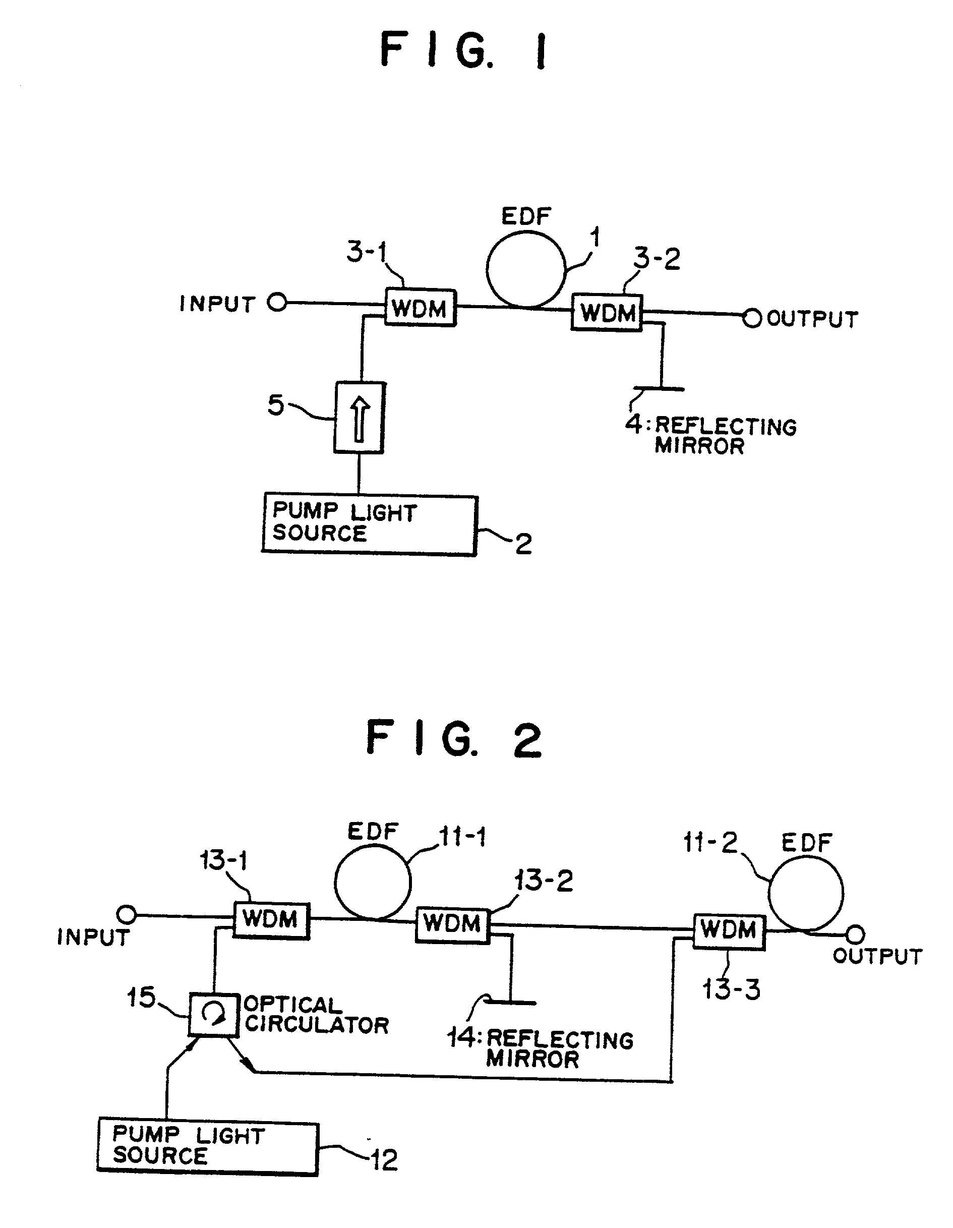
[0348] FIG. 25 is a block diagram showing a third preferred embodiment of the present invention. Referring to FIG. 25, the optical fiber amplifier shown includes an isolator 5-1, an optical demultiplexer-multiplexer 3-1, an erbium-doped-fiber (rare earth doped fiber) 1, another optical demultiplexer-multiplexer 3-2, and another isolator 5-3 disposed in this order from the input side. A pump source 2 is connected to the optical demultiplexer-multiplexer 3-1 by way of a further isolator 5-2. A reflecting mirror (reflection element) 4 is connected to the optical demultiplexer-multiplexer 3-2.
[0349] In particular, the optical fiber amplifier shown in FIG. 25 includes a first element for introducing pump light into an input end of the erbium-doped-fiber 1 by means of the optical demultiplexer-multiplexe-r 3-1, and a second element for demultiplexing residual pump light originating from the pump light introduced into the input end of the erbium-doped-fiber 1 by ...
PUM
 Abstract
Description
Claims
Application Information
 - R&D Engineer
- R&D Manager
- IP Professional
- Industry Leading Data Capabilities
- Powerful AI technology
- Patent DNA Extraction
Browse by: Latest US Patents, China's latest patents, Technical Efficacy Thesaurus, Application Domain, Technology Topic, Popular Technical Reports.
© 2024 PatSnap. All rights reserved.Legal|Privacy policy|Modern Slavery Act Transparency Statement|Sitemap|About US| Contact US: help@patsnap.com