Cryosurgical fluid supply

a technology of fluid supply and cryosurgical treatment, which is applied in the direction of cooling devices, lighting and heating devices, catheters, etc., can solve the problem of reducing the sensitivity of the system

Inactive Publication Date: 2002-01-24
BOSTON SCI SCIMED INC
View PDF0 Cites 89 Cited by
  • Summary
  • Abstract
  • Description
  • Claims
  • Application Information

AI Technical Summary

Benefits of technology

[0015] In another aspect, the invention provides a single-use cryogenic fluid delivery system for use with a cryogenic endovascular catheter so as to inhibit hyperplasia of a diseased blood vessel region of a patient body. The cryogenic delivery system comprises a cooling fluid container and a connector for coupling to the catheter. A cooling fluid path provides fluid communication from the container to the connector. The path has a seal, and a cryogenic cooling fluid is disposed within the fluid container. The cooling fluid has a quantity and is at a pressure such that the catheter will cool the blood vessel to a temperature in a predetermined temperature range so as to inhibit hyperplasia when the connector is coupled to the catheter and the seal is opened.
[0017] The container will often comprise a disposable cartridge having a frangible seal. The seal may be breached by a fitting which threadably engages a casing in which the container is received. Such disposable cartridges can safely maintain cryosurgical cooling fluids such as N.sub.2O at high pressures and in sufficient quantities to effect a variety of desired treatments. For example, the cartridge may contain about 5 to 30 grams of cooling fluid, and may contain N.sub.2O or other cooling fluids at a pressure between about 400 and 1000 psi.

Problems solved by technology

This intermittent flow may decrease sensitivity of the system to the particular configuration of the exhaust gas of flow path defined by a flexible catheter body disposed within the vascular system.

Method used


Image

  • Cryosurgical fluid supply
  • Cryosurgical fluid supply
  • Cryosurgical fluid supply

Examples


Embodiment Construction

[0027] The devices, systems, and methods of the present invention are related to co-pending U.S. patent application Ser. No. 09 / 203,011, filed on Dec. 1, 1998 for an Apparatus and Method for Cryogenic Inhibition of Hyperplasia, and to co-pending U.S. patent application Ser. No. ______ , filed Feb. 24, 1999 for a Cryogenic Angioplasty Catheter (Attorney Docket No. 18468-000400). These applications are assigned to the present assignee, and their full disclosures are incorporated herein by reference.

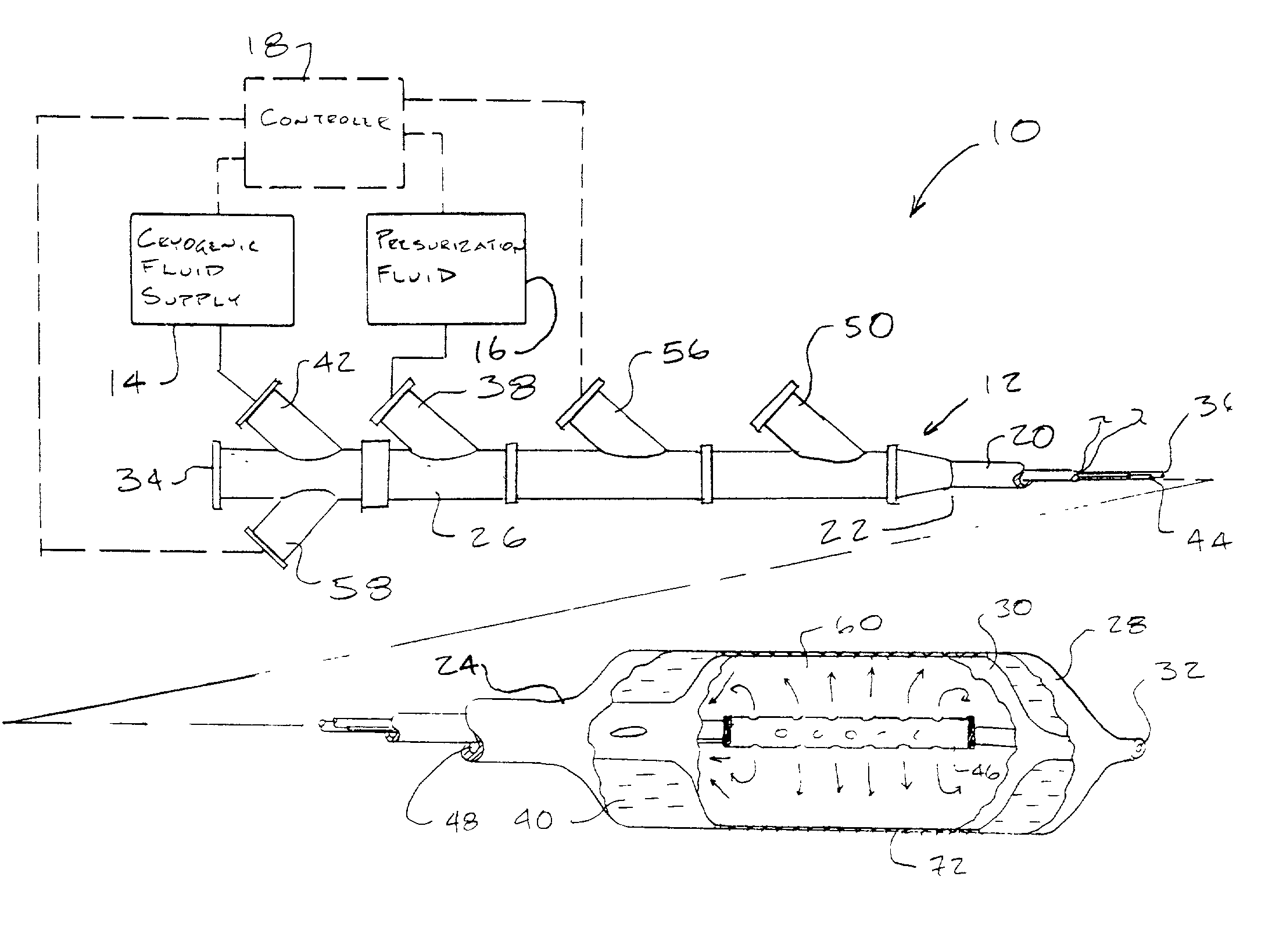
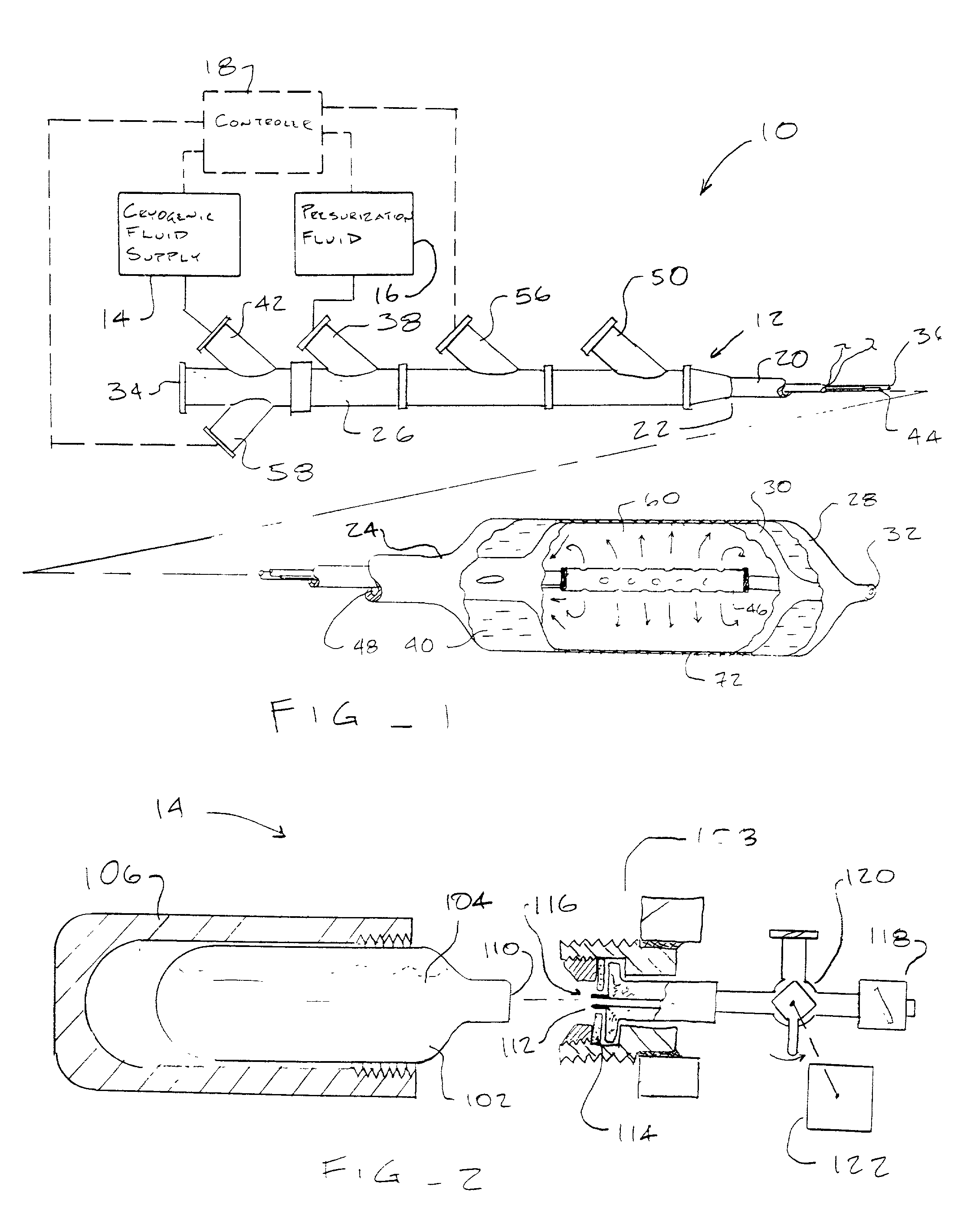
[0028] Referring now to FIG. 1, an exemplary system 10 is capable of treating a diseased vessel wall of a blood vessel using a combination of both angioplasty dilation and cryogenic cooling. In general, system 10 includes a catheter 12 coupled to a cryogenic fluid supply system 14 and an angioplasty pressurization system 16. One or both of cryogenic system 14 and pressurization system 16 may optionally be operatively coupled to a controller 18 for coordination of cooling and dilation. In so...


PUM


Abstract

Improved systems, devices, and methods for delivering cryogenic cooling fluid to cryosurgical probes such as cryosurgical endovascular balloon catheters take advantage of the transients during the initiation and termination of cryogenic fluid flow to moderate the treatment temperatures of tissues engaged by the probe. A flow limiting element along a cryogenic fluid path intermittently interrupts the flow of cooling fluid, often cycling both the fluid flow and treatment temperature. This can maintain the tissue treatment temperature within a predetermined range which is above the treatment temperature provided by a steady flow of cryogenic fluid. In another aspect, room temperature single-use cooling fluid cartridges are filled with a sufficient quantity of cryosurgical fluid to effect a desired endovascular cryosurgical treatment.

Description

[0001] 1. Field of the Invention[0002] The present invention relates generally to apparatus and methods for cryosurgical therapy. In a particular embodiment, the invention provides a cryosurgical fluid delivery system which makes use of transients in the cooling cycle to moderate the cooling effects of a cryosurgical endovascular balloon catheter.[0003] A number of percutaneous intravascular procedures have been developed for treating atherosclerotic disease in a patient's vasculature. The most successful of these treatments is percutaneous transluminal angioplasty (PTA). PTA employs a catheter having an expansible distal end (usually in the form of an inflatable balloon) to dilate a stenotic region in the vasculature to restore adequate blood flow beyond the stenosis. Other procedures for opening stenotic regions include directional arthrectomy, rotational arthrectomy, laser angioplasty, stenting, and the like. While these procedures have gained wide acceptance (either alone or in ...

Claims


Application Information

Patent Timeline
Patent Type & Authority Applications(United States)
IPC IPC(8): F25D3/10A61B17/00A61B17/22A61B18/02A61F7/12A61M25/00
CPCA61B18/02A61B18/0218A61B2017/00292A61B2018/0262A61B2018/0022A61B2018/0212A61B2017/22054
Inventor JOYE, JAMESWILLLIAMS, RICHARD S.WILLIAMS, RONALD
Owner BOSTON SCI SCIMED INC
Why Eureka
Try Eureka