Foam composite
- Summary
- Abstract
- Description
- Claims
- Application Information
AI Technical Summary
Benefits of technology
Problems solved by technology
Method used
Image
Examples
example i
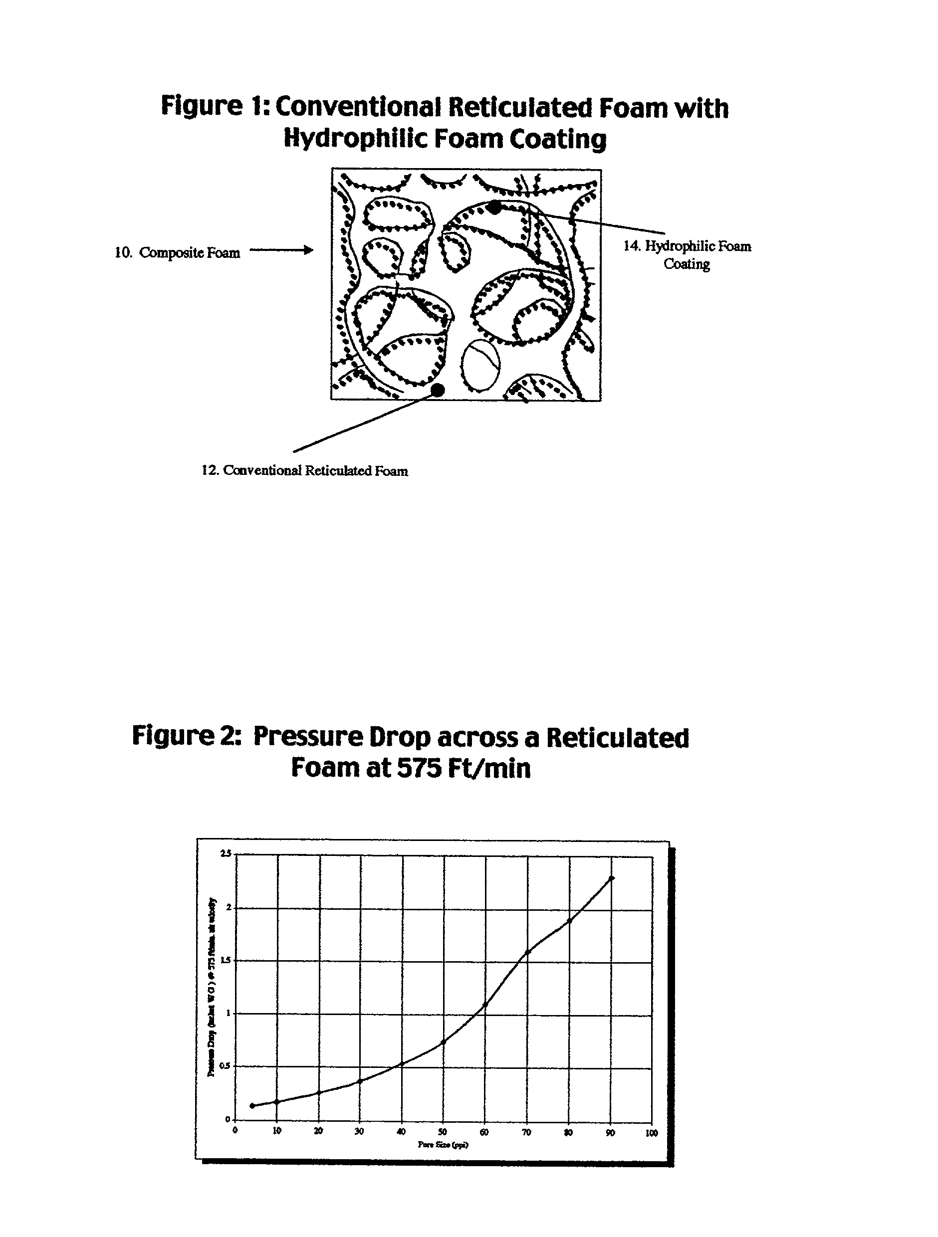
[0189] This example illustrates the preparation of foam composites by coating hydrophobic polyurethane scaffolds with an emulsion of polyurethane prepolymer.
[0190] Three (3) pieces of conventional hydrophobic reticulated foam having a pore size of 20 ppi such as Crest Foam, Grade S-20 were cut to 30.5 cm by 30.5 cm by 0.8 cm. Each weighed 16 grams. An emulsion was made using a mechanical mixer of a 0.1% Pluronic L62 (BASF Corp.) in water at ambient temperature and Rynel.RTM. (Grade B-1) hydrophilic polyurethane prepolymer (Rynel Ltd., Inc.). The emulsion was prepared by using 1 part prepolymer to 1.5 parts 0.1% Pluronic L62 solution. Three different amounts of the emulsion were immediately poured onto the three pieces of foam as shown in Table 5. In each case the entire emulsion was uniformly distributed onto the reticulated foam using a rolling pin. After curing, the entire amount of the prepolymer in the emulsion was found to form the coating of hydrophilic foam in the foam compos...
example 2
[0192] This example illustrates the preparation of foam composites by coating reticulated hydrophobic polyurethane scaffolds with a solution of polyurethane prepolymer. A solution of the prepolymer was dissolved in a solvent such as acetone. The weight of the coating was controlled by varying the viscosity of the solution.
[0193] Three solutions of 10%, 20% and 30% of Rynel.RTM. prepolymer in acetone were prepared at ambient temperature. Samples of Crest.RTM. reticulated polyurethane foam as described in Example 1 above were dipped into the Rynel.RTM. prepolymer solutions. They were immediately removed and allowed to drain. They were then hung in a fume hood and the acetone was allowed to evaporate as evidenced by an absence of the acetone odor. The foam samples were then immersed in water at 25.degree. C. for about 10 minutes to cure. The samples were then dried and reweighed. They were subsequently placed in water at 25.degree. C. for 1 hour, patted dry to remove surface water and ...
example 3
[0195] This example illustrates the preparation of foam composites by coating hydrophobic reticulated polyurethane scaffolds with undiluted polyurethane prepolymers having different viscosities. Prepolymers at three different temperatures were applied directly to Crest Foam.RTM. hydrophobic scaffolds as described below. The viscosity of commercial prepolymers was about 15,000 cps. at 25.degree. C. By heating the prepolymers their viscosity was lowered significantly. Three different foam composites having three different levels of open cell hydrophilic polyurethane coating were obtained.
[0196] Three (3) samples of the Rynel.RTM. prepolymer as described above were heated to 30.degree., 35.degree. and 40.degree. C. Three (3) samples of Crest.RTM. foam as described in Example 1 were each dipped into a prepolymer dip tank and then squeezed between rubber rollers. The samples were immediately immersed in water at 25.degree. C. to cure for about 30 minutes. The samples were dried and rewei...
PUM
| Property | Measurement | Unit |
|---|---|---|
| Length | aaaaa | aaaaa |
| Length | aaaaa | aaaaa |
| Length | aaaaa | aaaaa |
Abstract
Description
Claims
Application Information
 - R&D
- Intellectual Property
- Life Sciences
- Materials
- Tech Scout
- Unparalleled Data Quality
- Higher Quality Content
- 60% Fewer Hallucinations
Browse by: Latest US Patents, China's latest patents, Technical Efficacy Thesaurus, Application Domain, Technology Topic, Popular Technical Reports.
© 2025 PatSnap. All rights reserved.Legal|Privacy policy|Modern Slavery Act Transparency Statement|Sitemap|About US| Contact US: help@patsnap.com


