Process for producing friction plate having flat friction surface and system for producing the same

a technology of friction surface and friction plate, which is applied in the direction of fluid gearing, gearing, paper/cardboard containers, etc., can solve the problems of poor yield

Inactive Publication Date: 2002-02-28
FCC KK
View PDF0 Cites 5 Cited by
  • Summary
  • Abstract
  • Description
  • Claims
  • Application Information

AI Technical Summary

Problems solved by technology

However, the production of such friction linings generates a large amount of lining material scra

Method used


Image

  • Process for producing friction plate having flat friction surface and system for producing the same
  • Process for producing friction plate having flat friction surface and system for producing the same
  • Process for producing friction plate having flat friction surface and system for producing the same

Examples


Embodiment Construction

[0034] One embodiment of the present invention is explained below by reference to the appended drawings.

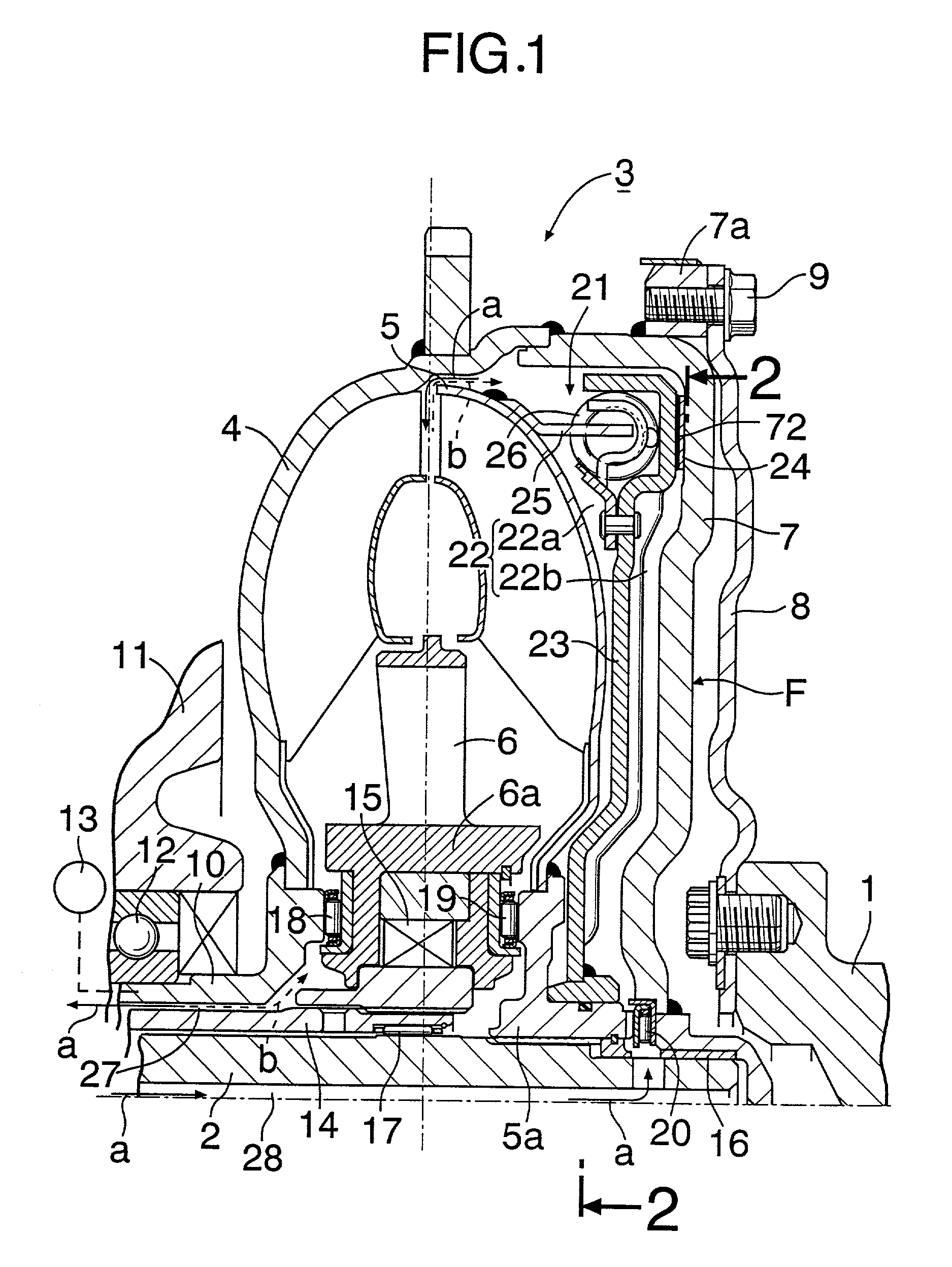
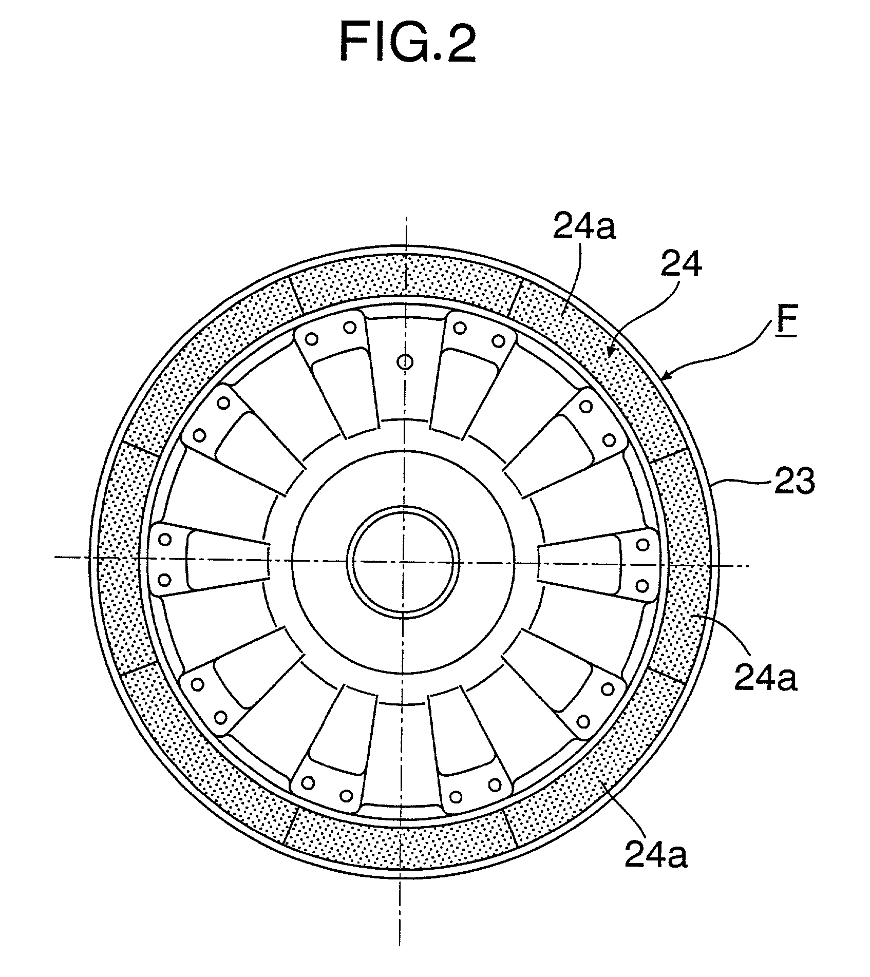
[0035] Firstly, a torque converter 3 having a lock-up clutch including a friction plate F produced in accordance with the present invention is explained by reference to FIGS. 1 and 2.

[0036] In FIG. 1 the torque converter 3 is placed between a crankshaft 1 of an automobile engine and an input shaft 2 of a multistage transmission. This torque converter 3 comprises a pump impeller 4, a turbine impeller 5 positioned so as to face the pump impeller 4, and a stator impeller 6 positioned in a space between these two impellers 4 and 5. The pump impeller 4 is formed integrally with a side cover 7 covering the back of the turbine impeller 5. This side cover 7 has a connecting ring 7a on the outer periphery thereof, and a drive plate 8 fixed to the output end of the crankshaft 1 is joined to the connecting ring 7a by bolts 9.

[0037] A tubiform pump shaft 10 connected to the centre of the pump...


PUM

PropertyMeasurementUnit
Pressureaaaaaaaaaa
Frictionaaaaaaaaaa

Abstract

A process for producing a friction plate having a flat friction surface includes a step of provisionally arranging a plurality of sector-shaped lining segments punched out of a friction lining tape material, in a generally annular form on an index table so as not to overlap with each other, a step of correcting the provisional arrangement of the lining segments into an annular form having no gaps between the lining segments by moving together the plurality of lining segments, provisionally arranged on the index table, towards the centre of the index table and a step of adhering the plurality of lining segments, correctly arranged in the annular form, to a surface of a core plate. A friction plate having a flat friction surface can thereby be obtained with low cost.

Description

[0001] 1. Field of the Invention[0002] The present invention relates to a process for producing friction plates having a flat friction surface that are used as, for example, friction plates for lock-up clutches of torque converters, and a system for producing the same.[0003] 2. Description of the Related Art[0004] The lock-up clutch of a torque converter is controlled so as to be in an ON state in its coupling region to directly connect a pump impeller to a turbine impeller, thereby eliminating any slip between the two impellers and thus improving the transmission efficiency. Such a lock-up clutch is known as disclosed in, for example, Japanese Patent Application Laid-open No. 5-71610. The ON state of the lock-up clutch is established as follows: the inner chamber of a lock-up clutch chamber is connected to a hydraulic oil supply side and the outer chamber is connected to a low pressure side, thereby increasing the pressure of the inner chamber relative to the pressure of the outer ...

Claims


Application Information

Patent Timeline
IPC IPC(8): F16H45/02F16D13/62F16D69/00F16D69/04
CPCF16D69/04Y10T156/1084F16H45/02F16H2045/0294Y10T156/1066Y10T29/49798Y10T156/13Y10T156/1754Y10T29/49789Y10T156/1322Y10T156/1092Y10T156/10Y10T156/1339Y10T156/1077F16D2069/0491
Inventor SHIMOI, HIROJITOBA, KENICHI
Owner FCC KK
Why Eureka
Try Eureka