Gas sensor and corresponding production method

a technology of gas sensor and production method, which is applied in the direction of superimposed coating process, instruments, coatings, etc., can solve the problem of inability to specify the thickness of the layer in the porous protective coating

Inactive Publication Date: 2002-02-28
ROBERT BOSCH GMBH
View PDF0 Cites 16 Cited by
  • Summary
  • Abstract
  • Description
  • Claims
  • Application Information

AI Technical Summary

Problems solved by technology

Herein, the rhodium coats the walls of the pores of the entire protective coating; as a ...

Method used


Image

  • Gas sensor and corresponding production method
  • Gas sensor and corresponding production method

Examples


Embodiment Construction

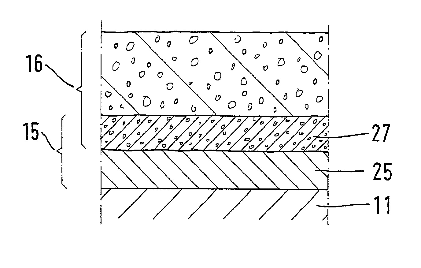
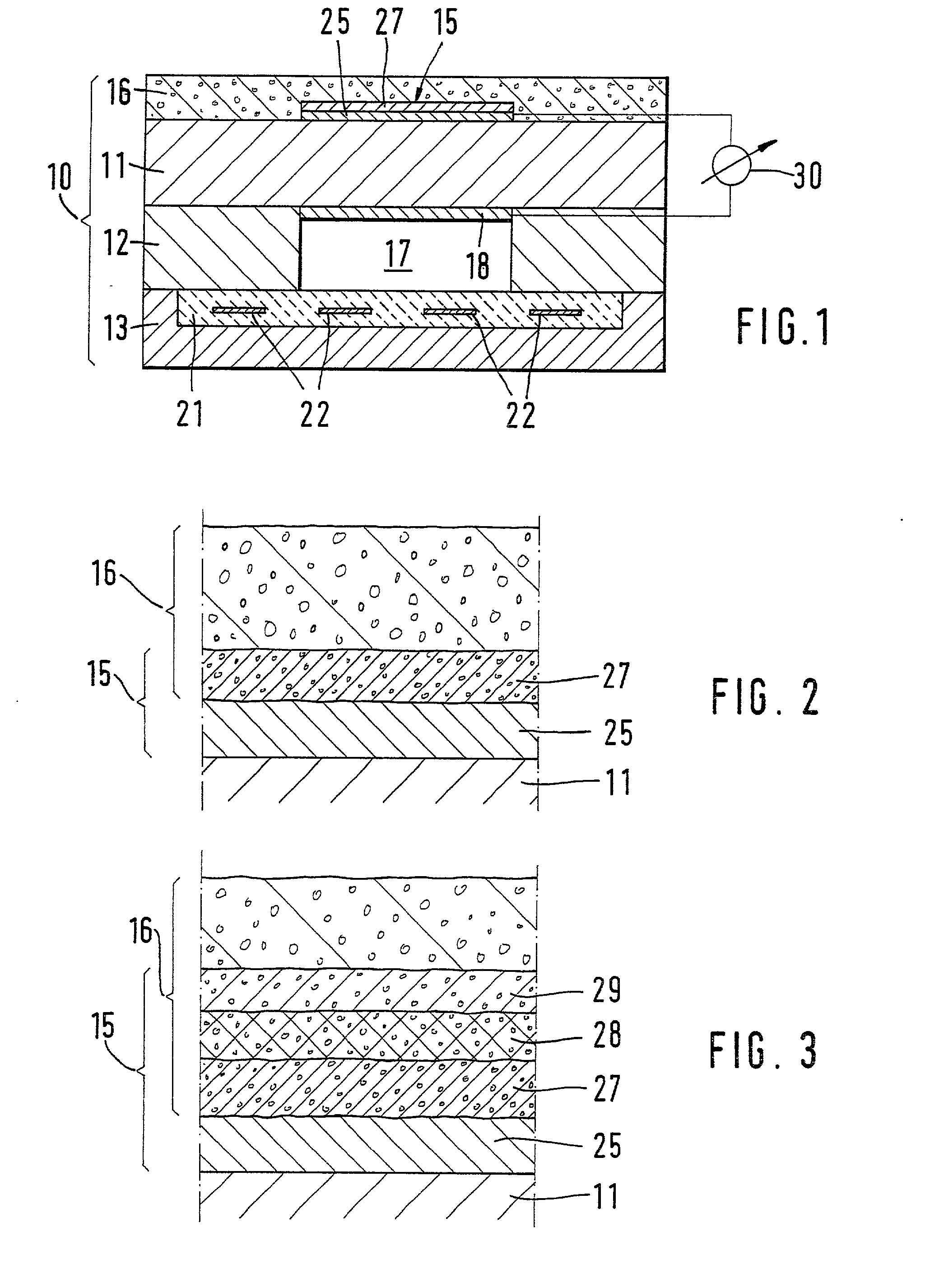
[0011] FIG. 1 shows a gas sensor having a sensor element basic body 10 whose structure corresponds to that of a Nernst-type oxygen sensor (lambda sensor). Basic body 10 includes, for example, a plurality of ceramic solid electrolyte foils 11, 12, 13, which are made of, for example, Y.sub.2O.sub.3-stabilized ZrO.sub.2. An outer measuring electrode 15, which is covered by a porous protective coating 16, is arranged on the outer large surface of first foil 11. Protective coating 16 is made of, for example, porous ZrO.sub.2 or Al.sub.2O.sub.3. A reference channel 17 is provided in second foil 12 and is connected to a reference atmosphere, e.g., air. A reference electrode 18, which is arranged on first foil 11 and faces measuring electrode 15, is arranged in reference channel 17. A heating device 22 is integrated into basic body 10, and on third foil 13 electrical insulating layers 21 are provided, in which heating device 22 is embedded. Heating device 22 is an electrical-resistor-type h...


PUM

PropertyMeasurementUnit
Temperatureaaaaaaaaaa
Electrical conductivityaaaaaaaaaa

Abstract

A gas sensor and a method for its manufacture are described. The gas sensor has a solid electrolyte (11) having at least one measuring electrode (15) and one porous protective coating (16). The measuring electrode (15) has an electrically conductive base layer (25) and a further layer (27), the further layer (27) being deposited in the pores of the porous protective coating (16) adjacent to the base layer (25) via galvanic deposition. In order to deposit the further layer (27) via galvanic deposition, the basic body (10), which has been fused with the base layer (25) and the protective coating (16) via vitrification, is immersed in a galvanizing bath, the base layer (25) being connected as the cathode.

Description

BACKGROUND INFORMATION[0001] The invention relates to a gas sensor according to the preamble of claim 1 and a method for manufacturing the gas sensor.[0002] From German Offenlegungsschrift 23 04 464 a probe is known in which a gold or silver electrode which does not catalyze establishment of equilibrium in the gas mixture and works in conjunction with a platinum electrode that does catalyze establishment of equilibrium in the measured gas is provided. The catalytically inactive electrode materials cause a competing reaction between the oxygen and the oxidizable and, respectively, reducible gas components to take place at that electrode. Even if adjustments have been made to ensure high lambda values, very little of the free oxygen that is conveyed along with the measured gas reacts with, for example, C.sub.3H.sub.6 or CO; as a result, free oxygen as well as C.sub.3H.sub.6 and, respectively, CO reach the three-phase boundary at the catalytically inactive electrode (non-equilibrium st...

Claims


Application Information

Patent Timeline
IPC IPC(8): G01N27/407G01N27/416G01N27/409
CPCG01N27/4071G01N27/4075G01N27/4077
Inventor SCHNEIDER, JENS STEFANNEUMANN, HARALDRIEGEL, JOHANNSTANGLMEIER, FRANKSCHUMANN, BERND
Owner ROBERT BOSCH GMBH
Why Eureka
Try Eureka