Insulative ceramic compact

a ceramic and compact technology, applied in ceramics, solid-state devices, electrical devices, etc., can solve the problems of low mechanical strength and q value type and proportion of deposited crystal phase, and low mechanical strength of substrate materials that can be fired at low temperatures

Inactive Publication Date: 2002-03-07
MURATA MFG CO LTD
View PDF0 Cites 23 Cited by
  • Summary
  • Abstract
  • Description
  • Claims
  • Application Information

AI Technical Summary

Benefits of technology

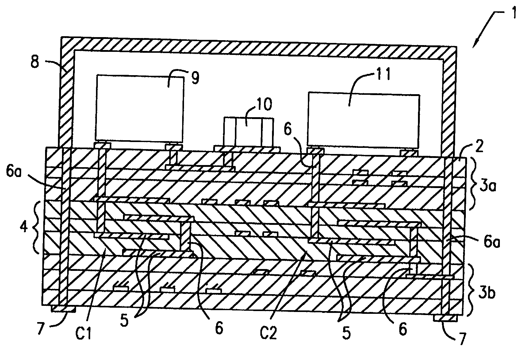
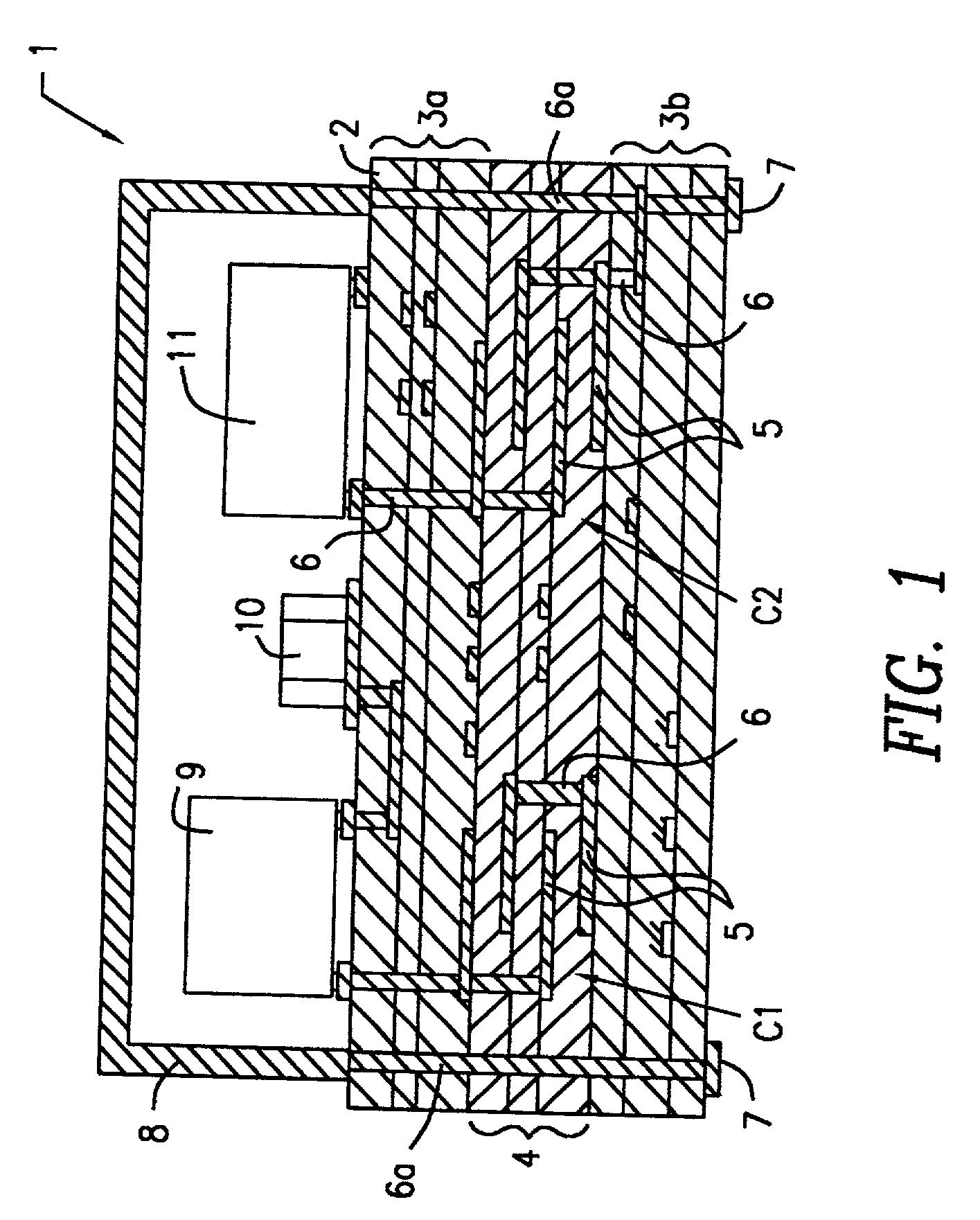
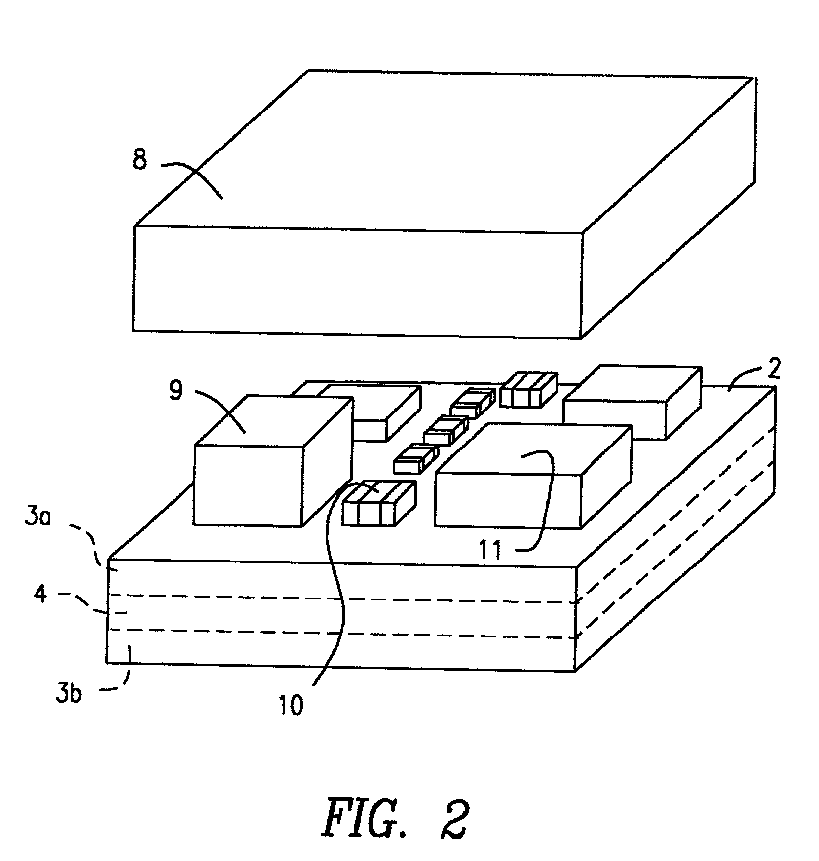
[0011] Another object of the present invention is to provide a multilayer ceramic substrate which is composed of the aforementioned insulative ceramic compact, can be obtained by firing at low temperatures, has a low relative dielectric constant and satisfactory high-frequency characteristics, and can be obtained by sintering in conjunction with a highly dielectric material having a high thermal expansion coefficient, as well as to provide a ceramic electronic part using the multilayer ceramic substrate.

Problems solved by technology

However, these conventional substrate materials that can be fired at low temperatures have low mechanical strengths and a low Q value, and the type and proportion of the deposited crystal phase are readily affected by the firing process.
Additionally, the substrate materials described in Japanese Unexamined Patent Application Publications No. 5-238774 and No. 8-34668 cannot be significantly sintered in conjunction with highly dielectric materials having a high thermal expansion coefficient.
In contrast, if it exceeds about 50% by weight, the resulting glass has an excessively high melting temperature.
If the content of boron oxide in terms of B.sub.2O.sub.3 is less than about 8% by weight, the melting temperature becomes excessively high, and if it exceeds 60% by weight, the resulting sintered compact has a decreased moisture resistance.
However, if the content of zinc oxide in terms of ZnO exceeds about 15% by weight, the resulting sintered compact may not become sufficiently dense in some cases.
However, if the content of the copper oxide exceeds about 3% by weight, the resulting insulative ceramic compact may have a decreased Q value.

Method used


Image

  • Insulative ceramic compact
  • Insulative ceramic compact
  • Insulative ceramic compact

Examples


example 2

[0095] Initially, a Mg(OH).sub.2 powder and a B.sub.2O.sub.3 powder as starting materials were weighed and mixed to yield mixtures each having a stoichiometric composition of Mg.sub.3B.sub.2O.sub.6 or Mg.sub.2B.sub.2O.sub.5, and the mixtures were wet-mixed for 16 hours, and were dried. The dried mixtures were calcined at 1400.degree. C. for two hours and were then crushed to thereby yield a Mg.sub.3B.sub.2O.sub.6 ceramic powder material and a Mg.sub.2B.sub.2O ceramic powder material, respectively. At least one of the two ceramic powder materials was used as a calcined material in the following procedures.

[0096] Next, 20 to 80% by weight of the above-prepared calcined material, a glass powder (sintering aid) having a composition indicated in Table 4, and ZnO and CuO were mixed in the proportions indicated in Table 5, and the mixture was granulated with an appropriate amount of a binder. Each of granulated insulative ceramic compositions, Samples 1 to 46, was molded at a pressure of 2...


PUM

PropertyMeasurementUnit
temperatureaaaaaaaaaa
temperaturesaaaaaaaaaa
frequencyaaaaaaaaaa

Abstract

An insulative ceramic compact is composed of a fired mixture of (A) a MgAl2O4, Mg3B2O6 and / or Mg2B205 ceramic powder, and (3) a glass powder including from about 13 to 50% by weight of silicon oxide in terms of SiO2, from 8 to 60% by weight of boron oxide in terms of B2O3, about 20% by weight or less of aluminum oxide in terms of A12O3, and from about 10 to 55% by weight of magnesium oxide in terms of MgO. The insulative ceramic compact can be obtained by firing at low temperatures of about 1000° C. or less, can be obtained by sintering with Ag or Cu, has a low dielectric constant and a high Q value, and is suitable for use in the high-frequency range.

Description

[0001] 1. Field of the Invention[0002] The present invention relates to an insulative ceramic compact for use in, for example, a multilayer circuit board. Specifically, the present invention relates to an insulative ceramic compact that can be advantageously used in a composite multilayer circuit board on which a semiconductor device or a variety of electronic parts is mounted, and can be obtained by firing in conjunction with a conductive material such as copper or silver.[0003] 2. Description of the Related Art[0004] Recent tendencies to accelerate and to use electronic equipment in higher frequencies keep on expanding. With such tendencies, demands for the accelerating, higher-density mounting and higher-density packing of electronic parts which are used in such electronic equipment are increasing. To satisfy these demands, multilayer circuit boards are conventionally used as substrates on which semiconductor devices and various electronic parts are mounted. In such a multilayer ...

Claims


Application Information

Patent Timeline
Patent Type & Authority Applications(United States)
IPC IPC(8): B32B18/00C04B35/053C03C10/02C03C14/00C04B35/03C04B35/443H01B3/08H01B3/12H01G4/12H05K1/03H05K3/46
CPCB32B18/00Y10T428/24926C03C2214/04C03C2214/20C04B35/03C04B35/443H01B3/087H01B3/12H05K1/0306H05K3/4629C04B2237/34C04B2237/343C04B2237/62C04B2237/68C04B2237/704C03C14/004H01L2224/16235C04B35/053H05K3/46H01G4/12
Inventor CHIKAGAWA, OSAMUMORI, NAOYASUGIMOTO, YASUTAKA
Owner MURATA MFG CO LTD
Why Eureka
Try Eureka