Implantable joint prosthesis

a joint prosthesis and implantable technology, applied in the field of implantable prostheses, can solve the problems of spinal disc herniation or rupture, debilitating symptoms, continuous degradation of spinal disc tissue,

Inactive Publication Date: 2002-03-21
SPINAL DYNAMICS CORP
View PDF0 Cites 615 Cited by
  • Summary
  • Abstract
  • Description
  • Claims
  • Application Information

AI Technical Summary

Problems solved by technology

Despite this process, in mature adults, spinal disc tissue degrades continuously over time.
Sufficiently advanced degeneration can lead to herniation or rupture of the spinal disc.
Herniation of a spinal disc can result in a number of debilitating symptoms, including intractable pain, weakness, and sensory loss.
Often discectomy alone cannot stop the progressive degeneration at the level of disc excision.
The discectomy and arthrodesis procedures can be problematic, however.
The grafting or fusion procedure has a variable success rate of about 80%, and even when succ...

Method used


Image

  • Implantable joint prosthesis
  • Implantable joint prosthesis
  • Implantable joint prosthesis

Examples


Embodiment Construction

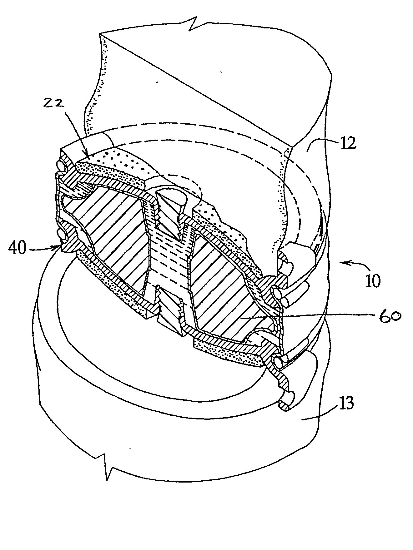
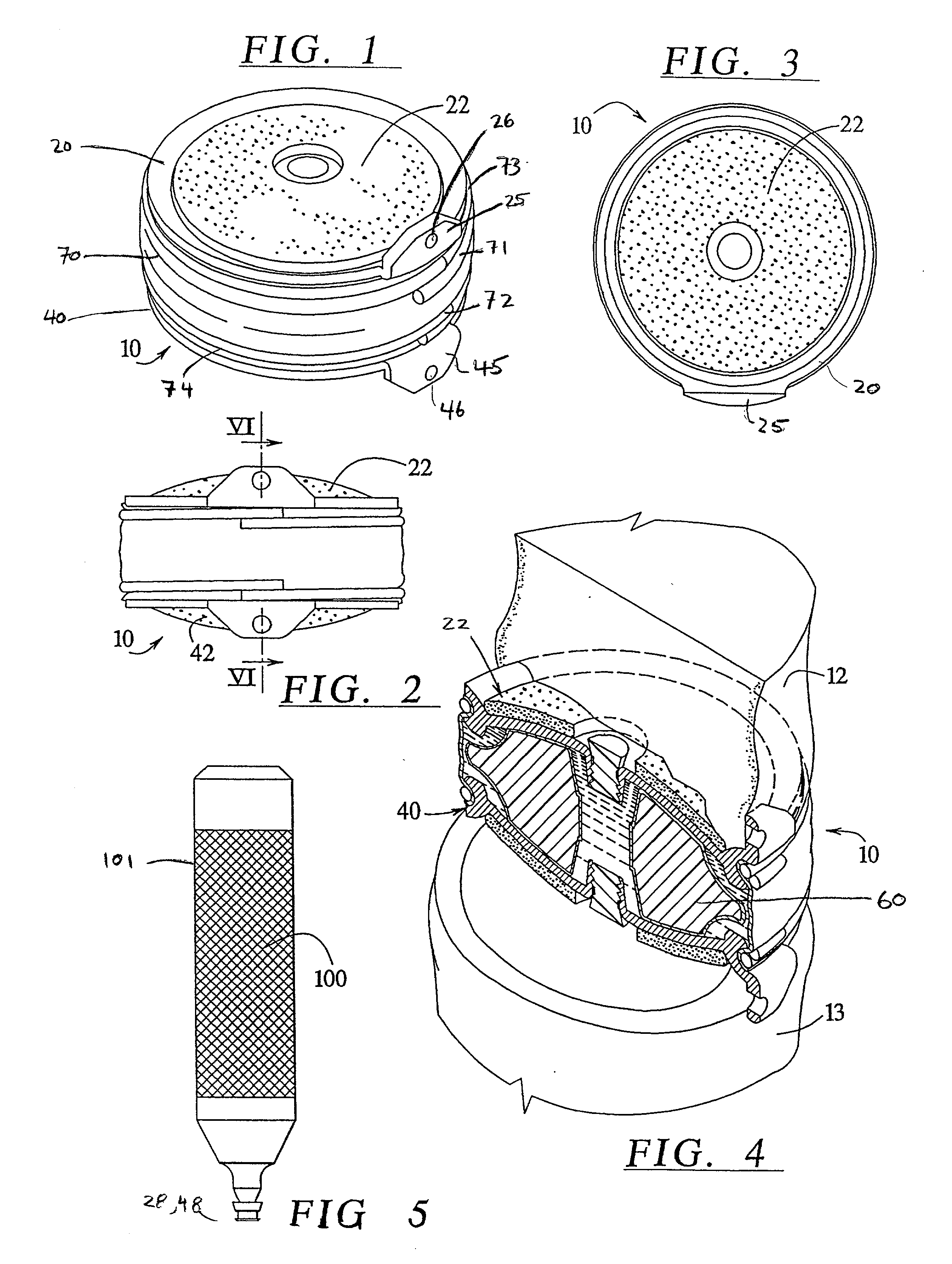
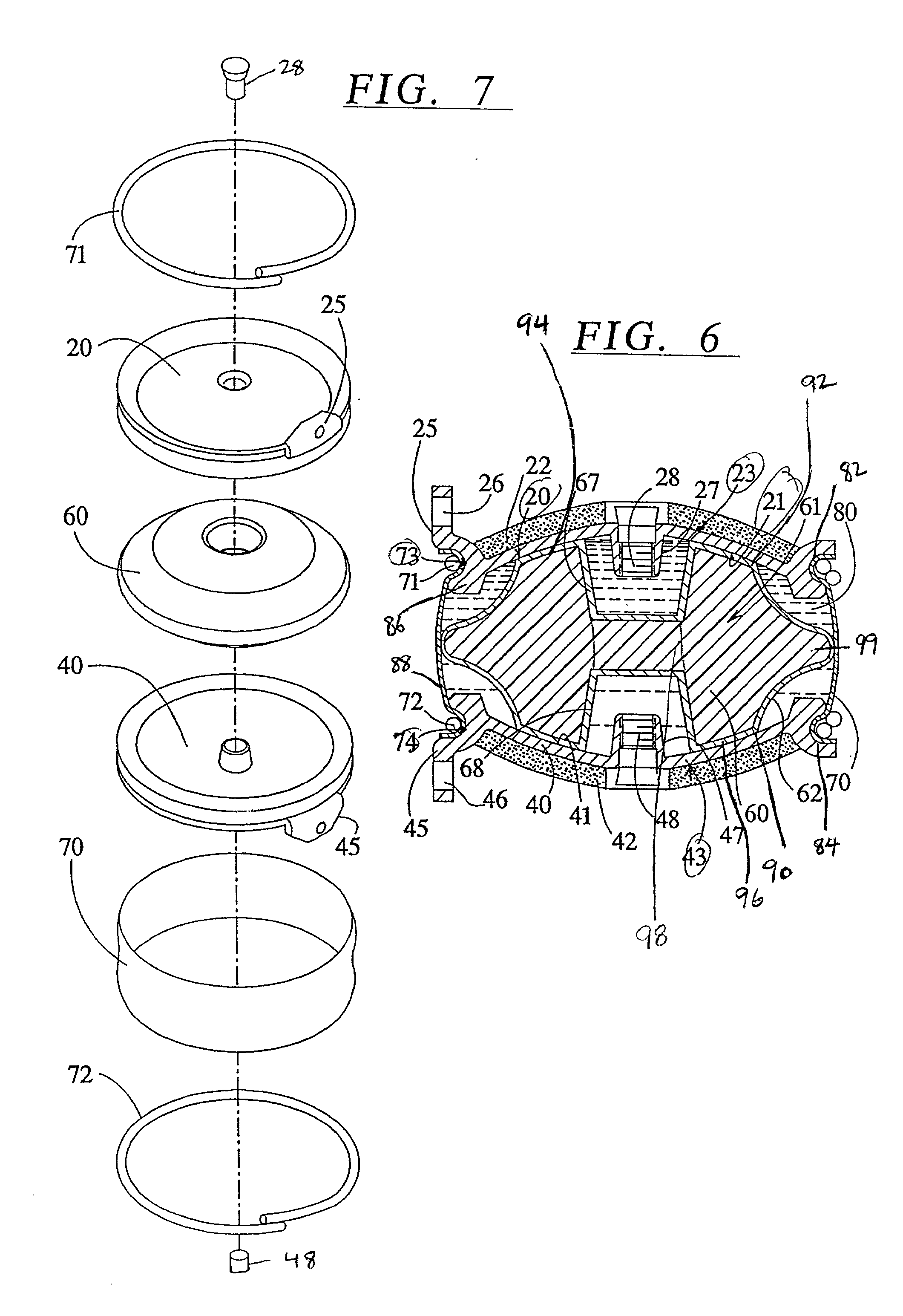
[0072] In broad aspect, the size and shape of the implant are substantially variable, and this variation will depend upon the joint geometry. Moreover, implants of a particular shape can be produced in a range of sizes, so that a surgeon can select the appropriate size prior to or during surgery, depending upon his assessment of the joint geometry of the patient, typically made by assessing the joint using CT, MRI, fluoroscopy, or other imaging techniques.

[0073] The rigid opposing plates or shells can be made of any rigid, biocompatible material, but are generally made of a biocompatible metal, such as stainless steel, cobalt chrome, ceramics, such as those including Al.sub.2O.sub.3 or Zr.sub.2O.sub.3, or titanium alloy. ASTM F-136 titanium alloy has been found to be particularly suitable. As indicated above, the outer surface of the rigid opposing plates or shells are rough, in order to restrict motion of the shells relative to the bone surfaces that are in contact with the plates....


PUM


Abstract

The invention relates to a surgical implant that provides an artificial diarthroidal-like joint, suitable for use in replacing any joint, but particularly suitable for use as an intervertebral disc endoprosthesis. The invention contains two rigid opposing shells, each having an outer surface adapted to engage the surfaces of the bones of a joint in such a way that the shells are immobilized by friction between their outer surfaces and the surfaces of the bone. These outer surfaces are sufficiently rough that large frictional forces strongly resist any slippage between the outer surface and the bone surfaces in the joint. They may be convex, and when inserted into a milled concavity, are immediately mechanically stable. Desirably, the outer surfaces of the shells are adapted to allow for bony ingrowth, which further stabilizes the shells in place. The inner surfaces of the shells are relatively smooth, and adapted to slide easily across a portion of the outer surface of a central body disposed between the shells. The central body has a shape that cooperates with the shape of the inner surface of the shell so as to provide a range of motion similar to that provided by a healthy joint. A flexible sheath extends between edges of the opposing shells. The inner surface of this sheath, together with the inner surfaces of the rigid shells, defines a cavity encasing the central body. At least a portion of this cavity is filled with a fluid lubricant, further decreasing the frictional force between inner surfaces of the shell and the surface of the central body.

Description

[0001] This application claims benefit under 35 U.S.C. .sctn. 119(e) of Provisional U.S. Ser. No. 60 / 223,863, filed 8 Aug. 2000, and entitled INSTRUMENTATION AND METHOD FOR IMPLANTING A PROSTHETIC INTERVERTEBRAL BODY and of Provisional U.S. Ser. No. 60 / ______, entitled GRAVITY ASSISTED LOCALIZATION SYSTEM, filed Jan. 31, 2001 under Express Mail Label Number EL674301928US.[0002] 1 . Field of the Invention[0003] The invention relates to implantable prostheses that are suitable for replacement of diarthroidal or arthroidal joints by creating an artificial diarthroidal-like joint at the site of the implant.[0004] In a particular embodiment, the invention relates to implantable prostheses serving as replacements for at least a portion of the intervertebral disc material, i.e., a spinal disc endoprostheses suitable for implantation in vertebrates, including humans.[0005] 2. Description of Related Art[0006] Many joints in the human body, such as hips, knees, shoulders, etc., are diarthroid...

Claims


Application Information

Patent Timeline
IPC IPC(8): A61B17/02A61B17/16A61B17/17A61B19/00A61F2/00A61F2/30A61F2/44A61F2/46
CPCA61B17/02A61B17/1671A61B17/1757A61B19/20A61B19/26A61B2017/0256A61B2017/1602A61B2019/304A61F2/30742A61F2/30744A61F2/442A61F2/4425A61F2/4611A61F2002/30204A61F2002/30235A61F2002/30474A61F2002/30499A61F2002/30528A61F2002/30563A61F2002/30578A61F2002/30616A61F2002/30662A61F2002/30673A61F2002/30682A61F2002/30769A61F2002/30772A61F2002/443A61F2220/0025A61F2230/0065A61F2230/0069A61F2310/00017A61F2310/00023A61F2310/00029A61F2310/00203A61F2310/00239A61B90/10A61B90/50A61B2090/034A61F2002/302A61F2002/30495
Inventor BRYAN, VINCENTKUNZLER, ALEX
Owner SPINAL DYNAMICS CORP
Why Eureka
Try Eureka