Quadrature oscillator with phase error correction

a phase error correction and oscillator technology, applied in pulse manipulation, phase-modulated carrier systems, pulse techniques, etc., can solve the problems of high cost, high noise, and poor communication effect, and achieve the effect of increasing the amount of data

Inactive Publication Date: 2002-04-04
M RED INC
View PDF11 Cites 71 Cited by
  • Summary
  • Abstract
  • Description
  • Claims
  • Application Information

AI Technical Summary

Benefits of technology

0007] It is desired to detect and reduce or otherwise eliminate phase errors between the I/Q carrier signals of a quadrature o...

Problems solved by technology

Wired networks provide a certain level of convenience but have many limitations such as various cable management and convenience issues.
The typical environment for wireless communications, however, is very noisy and not optimal for communications.
For example, most homes and workplaces include many electronic devices resulting in an electronically noisy environment that may interfere with WLAN communications, such as microwave ovens, garage door openers, radios, television sets, computer systems, etc.
For example, most environments or rooms include multiple reflective services, creating multipath noise.
Movement of items or devices or the like such as hands, bodies, jewelry, mouse pointers, etc., or activation of electronic devices, such as cooling fans or the like, affects the overall wireless communication path and potentially degrades wireless communication performance.
Because of the dynamic and unpredictable environment through ...

Method used


Image

  • Quadrature oscillator with phase error correction
  • Quadrature oscillator with phase error correction
  • Quadrature oscillator with phase error correction

Examples


Embodiment Construction

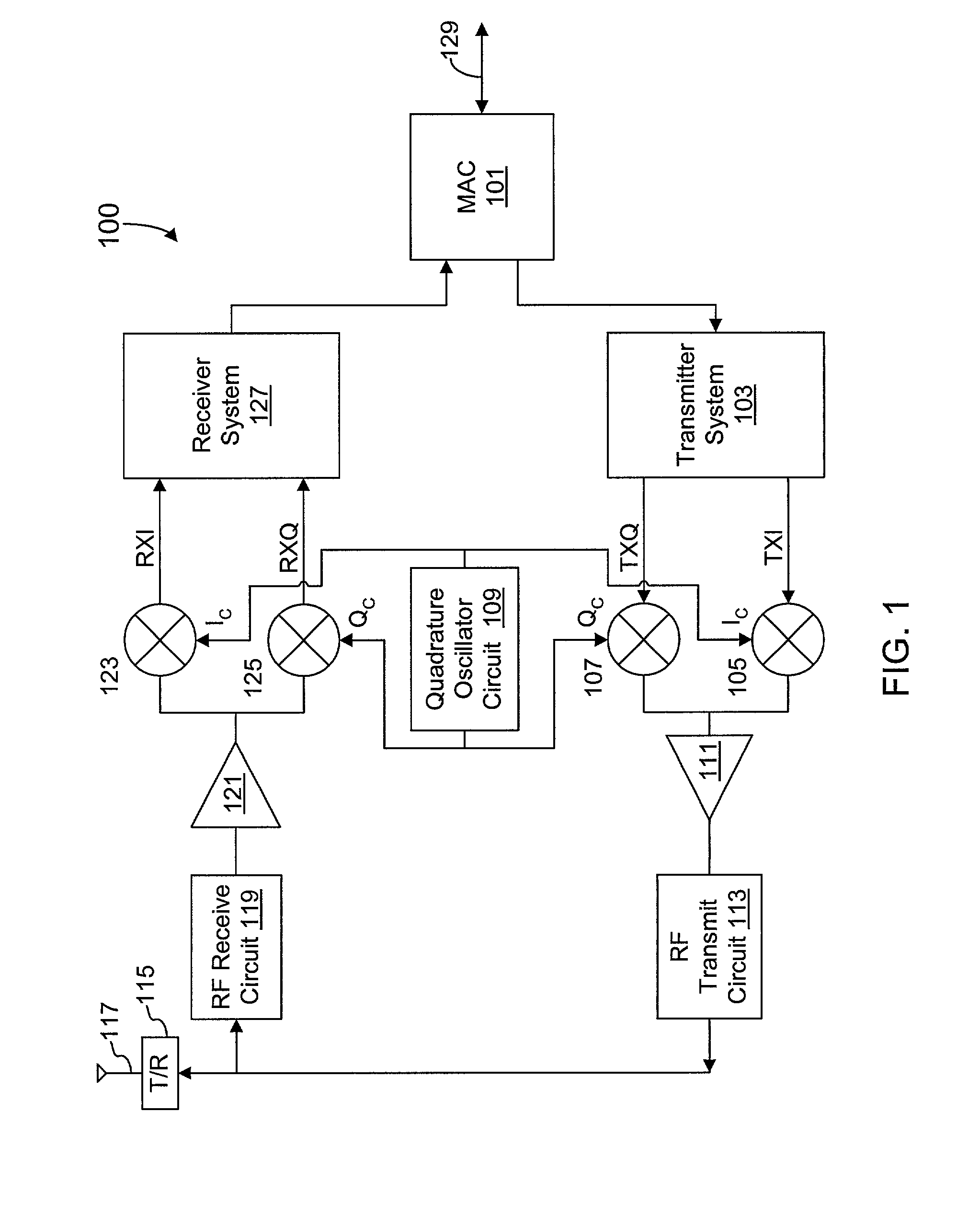
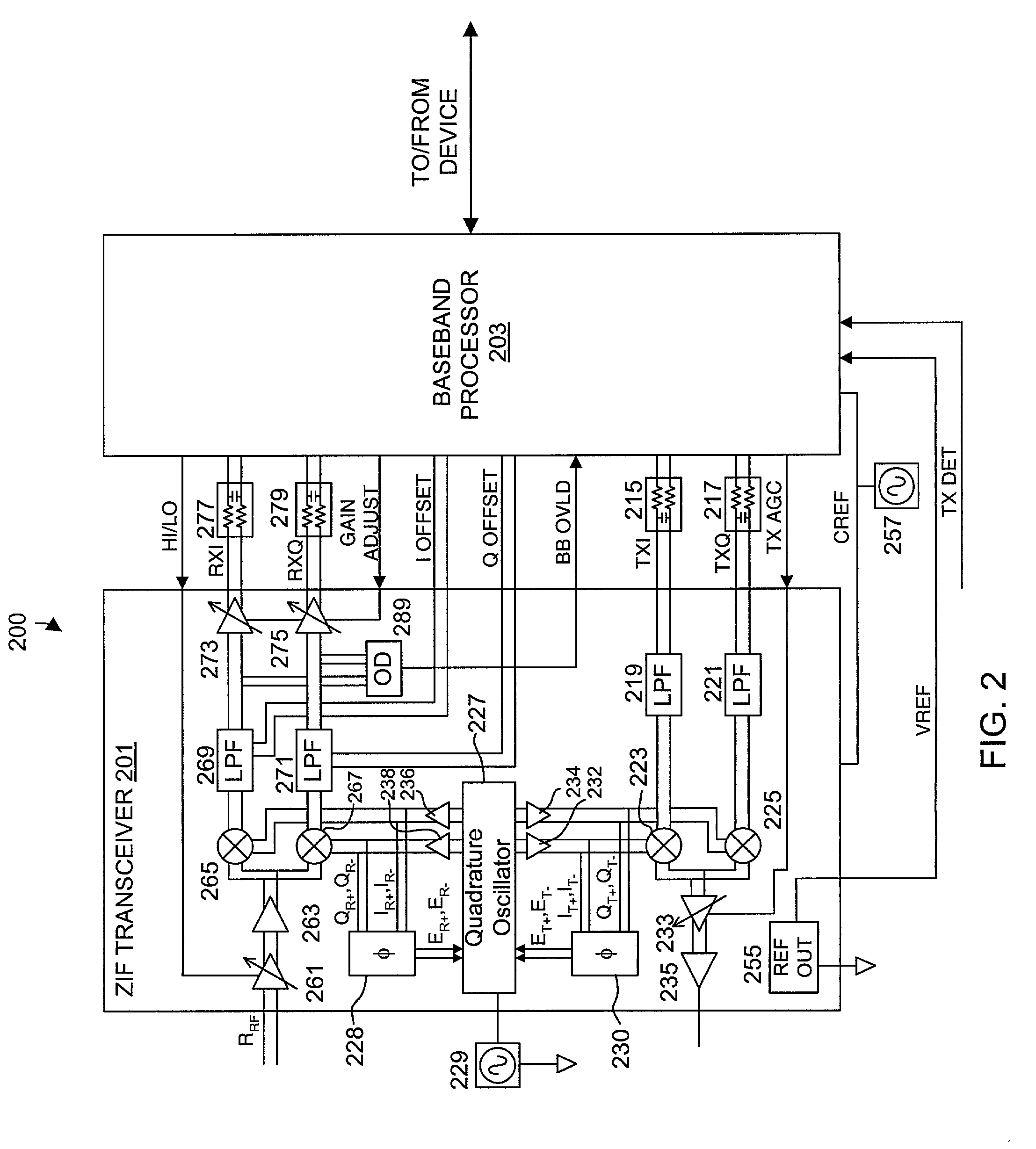
[0025] FIG. 1 is a simplified block diagram of an exemplary wireless transceiver 100 that includes a quadrature oscillator circuit 109 with phase error correction implemented according to an embodiment of the present invention. The wireless transceiver 100 may utilize any desired carrier frequency and modulation technique to achieve any of the several corresponding data throughputs. For example, the wireless transceiver 100 may be configured to operate according to the Institute of Electrical and Electronics Engineers (IEEE) 802.11b with a carrier frequency of approximately 2.4 gigahertz (GHz) and with data throughputs of 1, 2, 5.5 or 11 megabits per second (Mbps). Alternatively, the wireless transceiver 100 may be configured according to IEEE 802.11a with a carrier frequency of approximately 5 GHz for achieving data throughputs of 6, 12, 24, 36 or 54 megabits per second (Mbps). The direct sequence spread spectrum (DSSS) modulation technique may be used, although many communication ...


PUM


Abstract

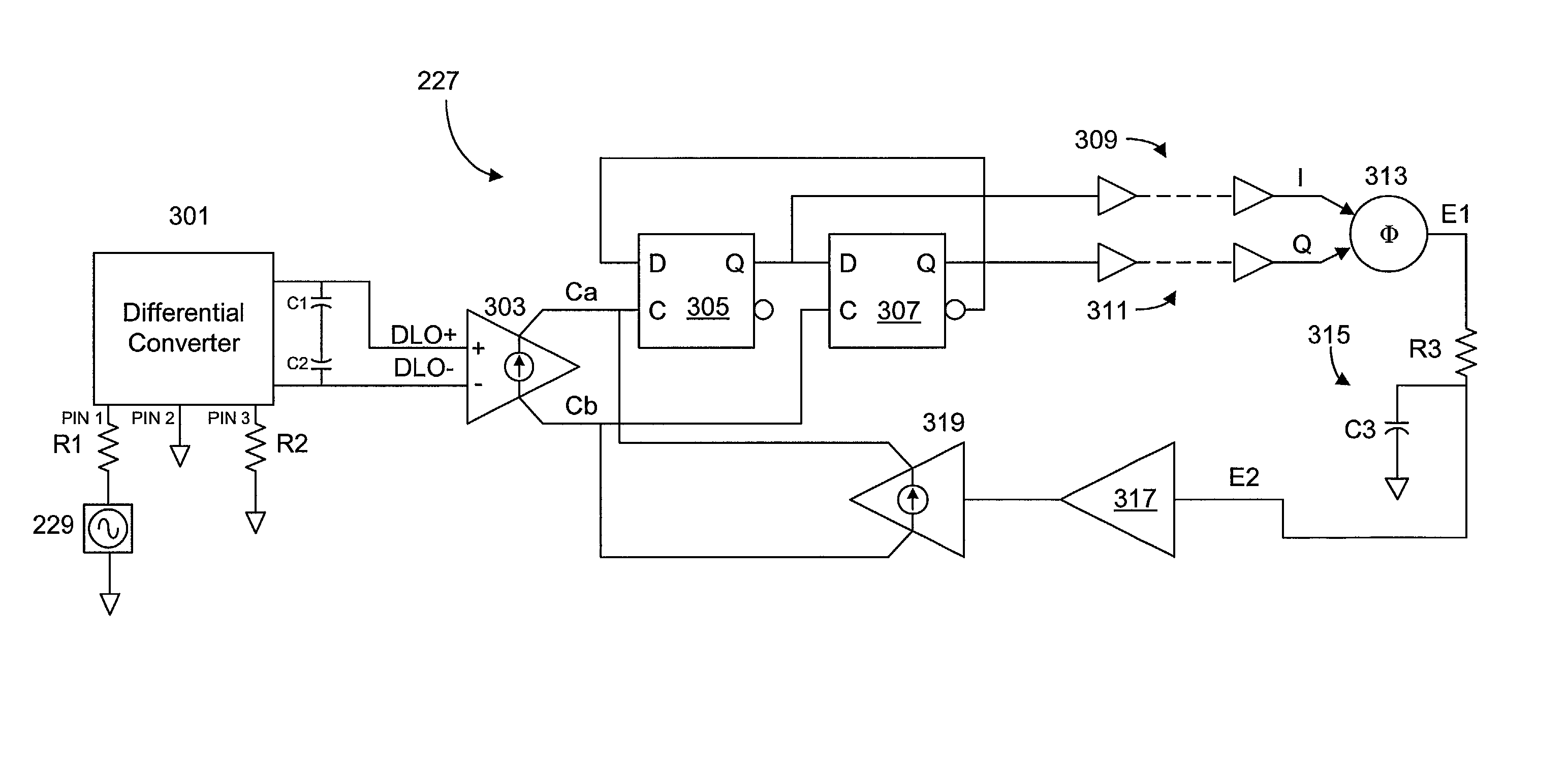
A quadrature oscillator with phase error correction including a local oscillator that generates a single-ended clock signal, a single-ended to differential converter that converts the clock signal to a differential clock signal, a quadrature generator that converts the differential clock signal into I and Q carrier signals, a phase error detector that measures a phase error between the I and Q carrier signals, and a feedback amplifier that modifies the differential clock signal based on measured phase error. The feedback amplifier applies the measured phase error as a DC offset to an AC differential clock signal. A transconductor converts the differential clock voltage signal into two pairs of differential current clock signals, where the quadrature generator generates I and Q current signal outputs from the two pairs of differential current clock signals. The phase error detector generates a phase error voltage, and the feedback amplifier includes a transconductance stage that converts phase error voltage into a DC correction current and that adds the correction current to each of the two pairs of AC differential current clock signals.

Description

CROSS-REFERENCE TO RELATED APPLICATION(S)[0001] The present application is a continuation-in-part (CIP) of U.S. patent application entitled "A Calibrated DC Compensation System For A Wireless Communication Device Configured In A Zero Intermediate Frequency Architecture", Ser. No. 09 / 677,975, filed Oct. 2, 2000, which is hereby incorporated by reference in its entirety. The present application is related to U.S. patent application entitled "System And Method For Detecting And Correcting Phase Error Between Differential Signals", Ser. No. ______, filed concurrently herewith, which is hereby incorporated by reference in its entirety.[0002] The present invention relates to modulation techniques, and more particularly to a quadrature oscillator with phase error correction that provides in-phase (I) and quadrature phase (Q) carrier signals.DESCRIPTION OF RELATED ART[0003] Many small networks are commonly connected through a set of wires. Wired networks provide a certain level of convenien...

Claims


Application Information

Patent Timeline
IPC IPC(8): H03G3/20H03B27/00H03D3/00H03G3/30H03L7/00H03L7/081H03L7/085H04B1/30H04L27/00H04L27/20H04L27/36
CPCH03B27/00H03D3/008H03D3/009H04L2027/0016H03L7/085H04B1/30H04L27/0014H03L7/0812
Inventor STRAUB, A. MICHAELPRENTICE, JOHN S.
Owner M RED INC
Why Eureka
Try Eureka