Method for measuring scan beam light quantity distribution in scan optical system, measurement apparatus thereof, measurement evaluation apparatus thereof, and image formation apparatus using the measurement evaluation apparatus

Inactive Publication Date: 2002-04-18
RICOH KK
View PDF0 Cites 18 Cited by
  • Summary
  • Abstract
  • Description
  • Claims
  • Application Information

AI Technical Summary

Benefits of technology

[0031] Further, the light source is subjected to blinking control at a predetermined interval so as to modulate the scan beam emitted from the light source on pixel basis and receive the scan beam by the light receiving element at an imaging position,. When analyzing the light quantity distribution of the scan beam received by the light receiving element, a dot center-of-gravity position of respective scan beams is calculated from the analyzed light quantity distribution data to a plurality of dots measured within scanning region of the scan beam, so as to find distance-between-dot-position of distant two points. By repeatedly calculating this distance between respective adjacent dots, and to find a magnification error of the scan optical system from data in the horizontal scan direction of the scan beam obtained in such a way as to find repeatedly the distance-between-dot-position in every adjacent dots. In this case, it is possible to measure the magnification error of the scan optical system with high accuracy.
[0060] Also, the electrophotographic image formation apparatus is provided with the above-described scan beam measurement apparatus, and it is possible to execute measurement evaluation of the position of the scan beam of the scanning optical apparatus for executing exposure scanning of the electrostatic latent image depending on this apparatus. Accordingly, the electrophotographic image formation apparatus is capable of giving the same action and effect as that of the above scan beam measurement evaluation apparatus.

Problems solved by technology

Now, when the optical elements constituting the scan optical system have abnormalities such as profile irregularities (undulation), a surface defect, an internal defect, and so forth, the scanning position of the scan beam on the photosensitive body is deviated in the horizontal scan direction, and out-of-focus in the depth direction of the scan beam occurs.
Such position deviation deteriorates the peak light quantity of the scan beam and / or affects size of diameter and shape of the scan beam, thus causing faulty image formation.
However, in this conventional measurement method of the beam diameter, when executing measurement across the entire scanning area in every predetermined pitch, for instance, when executing measurement across the entire scanning area in every 1 mm, the measurements require enormous measuring times. Further, since the measurement is executed in stationary state of the beam, there is problem that beam characteristic in scanning state cannot be measured.
Furthermore, the beam diameter is measured in the position of a fixed ratio to peak intensity of the beam and accordingly, there is the problem that evaluation based on absolute amount of the intensity is not executed.
However, in such a conventional measurement method, there are following problems, namely:
However, measurement of light quantity distribution of the scan beam cannot be measured by this measurement method.
However, this measurement method cannot execute measurement evaluation relative to neighboring beam diameters actually about degree of one pixel apart caused by restriction posed by arrangement of the beam position sensors.
However, this method can measure the beam diameter at only predetermined position, and it cannot measure the beam diameter at arbitrary position in the entire horizontal scan direction.
However, in this measurement method, since accurate distance between respective beam position sensors is not known, it is impossible to detect distance between two points of beam, accordingly, evaluation of magnification error cannot be executed.
{circle over (5)} Still moreover, the measurement method for measuring beam position by three positions of the beam position sensors cannot execute measurement evaluation of accurate scanning line bend-amount, because there is restriction in the number of arranged beam position sensors.
However, the conventional apparatus cannot emit beam of arbitrary light emission pattern to the stage side beam detecting sensor that moves toward the predetermined position, and also does not enable the scan beam to emit a light repeatedly because repeatability of light emission of the beam to the predetermined position is bad.
Also, in this conventional measurement method of the beam diameter, when executing measurement across the entire scanning area, for instance, in every 1 mm, the measurements require enormous measuring times. Further, since the measurement is executed in stationary state of the beam, also there is malfunction that beam characteristic in scanning state cannot be measured.
However, when positions are stored at the time of generation of scanning reference signal and the beam positions are detected in the entire scanning area, error in the measurement time described later is generated, and since this error cannot be ignored with respect to position instrumentation error, thus it becomes problem when executing position instrumentation with high accuracy.
However, by adding the triggering PD, not only apparatus configuration becomes complicated, but also there is malfunction that configuration of control becomes complicated in that it is necessary to execute lighting control such that the scan beam enters certainly the triggering PD.
Further, in the above-described movable stage, if there is fluctuation in connection with its intervals of time from position detecting synchronizing signal until the time that position detection is executed actually, it leads to error of the beam position in the same manner.
Since the beam diameter of the scan system is smaller than .sub.--100 .mu.m, there is malfunction that measurement accuracy deteriorates significantly.
Accordingly apparatus cost rises in comparison with the case that control is executed by use of general-purpose PC.
Also, on the occasion of high density measurement, the two-dimensional area type light receiving element is made to use on the detection optical system, therefore, detection region cannot be taken largely, as a result, it is necessary to butt detection data together, however in the meantime, since the operation can be made to execute entrapment of position information of the detection optical system accompanied with movement in high speed and high accuracy, it is possible to detect absolute position of the scan beam on the basis of the position and coordinate on the image of the two-dimensional area light receiving sensor thus obtained without increasing absolute positioning accuracy of the movement mechanism, and it is possible to measure accurately the magnification error or the scanning line bend-amount on the entire scanning area of the scan optical system.

Method used


Image

  • Method for measuring scan beam light quantity distribution in scan optical system, measurement apparatus thereof, measurement evaluation apparatus thereof, and image formation apparatus using the measurement evaluation apparatus
  • Method for measuring scan beam light quantity distribution in scan optical system, measurement apparatus thereof, measurement evaluation apparatus thereof, and image formation apparatus using the measurement evaluation apparatus
  • Method for measuring scan beam light quantity distribution in scan optical system, measurement apparatus thereof, measurement evaluation apparatus thereof, and image formation apparatus using the measurement evaluation apparatus

Examples


first embodiment

[0085] Hereinafter, the present invention will be described with reference to the attached drawing.

[0086] [Configuration]

[0087] FIG. 1 to FIG. 8 are views illustrating a scan beam light quantity distribution measurement method (scan beam light quantity distribution measurement / evaluation method) and a measurement apparatus (measurement / evaluation apparatus) of a scan optical system according to a first embodiment of the present invention.

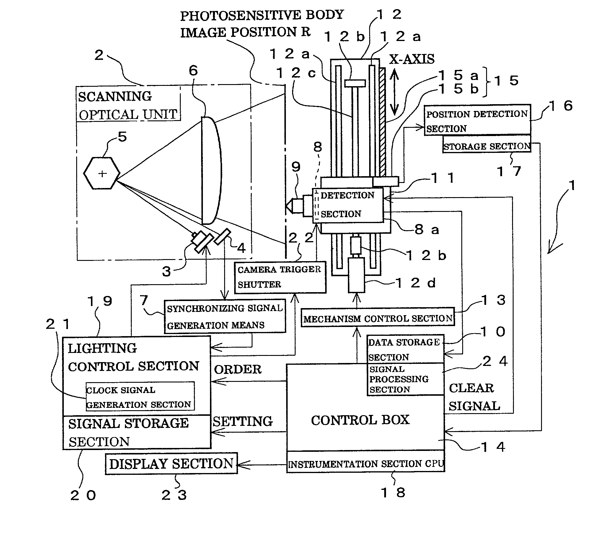
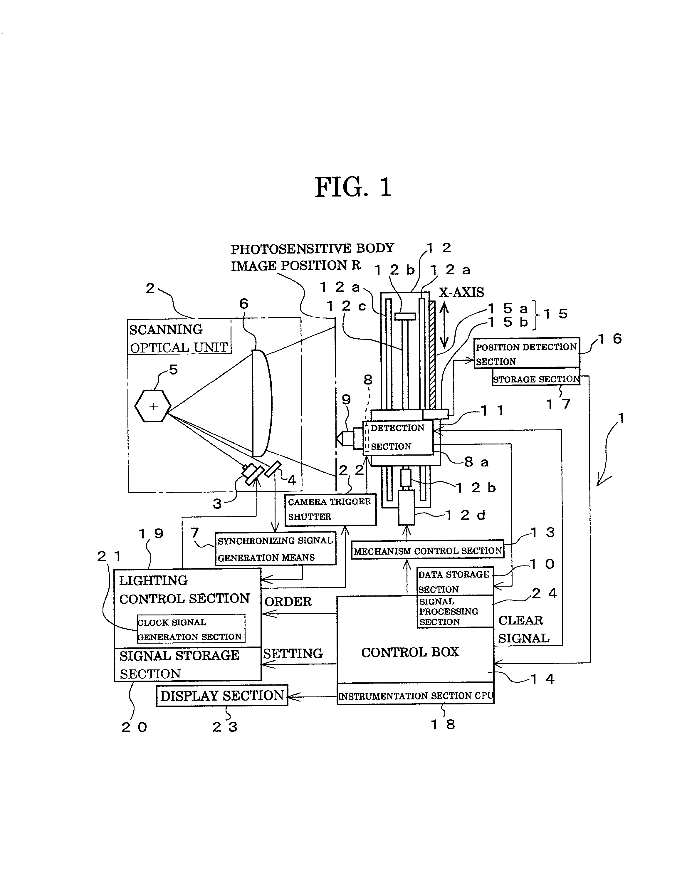
[0088] Firstly, explanation refers to configuration. FIG. 1 is a view illustrating the scan beam light quantity distribution measurement apparatus. In the present embodiment, measurement of light quantity distribution is performed by setting a scan optical system 2 to this scan beam light quantity distribution measurement apparatus (scan beam measurement / evaluation apparatus) 1.

[0089] The scan optical system 2 is provided with a laser light source (light source) 3 consisting of a laser diode, a light receiving sensor 4 consisting of a photo diode as...

second embodiment

[0156] [Second Embodiment]

[0157] [Configuration]

[0158] FIG. 9 to FIG. 13 are views illustrating second embodiment of a scan beam light quantity distribution measurement method and measurement apparatus of scan optical system according to the present invention, and in the present embodiment, the same number is added to the same configuration as that of the first embodiment to omit explanation.

[0159] In the present embodiment, the lighting control section 19 is made to execute lighting control of the laser light source 3 with constant intervals so as to modulate the scan beam emitted from the laser light source 3 with a pixel unit, and the two-dimensional area light receiving sensor 8 receives the scan beam at the photosensitive body image position R, then the control box 14 analyzes the light quantity distribution of the scan beam received by the two-dimensional area light receiving sensor 8. At the time that the light quantity distribution of the scan beam is made to analyze, distan...

third embodiment

[0205] [Third Embodiment]

[0206] FIG. 14 is a block diagram illustrating third embodiment of the scan beam light quantity distribution measurement apparatus according to the present invention, and for explaining outline configuration of the scan beam light quantity distribution measurement apparatus (scan beam measurement evaluation apparatus) 1 for measuring to be evaluated scan beam of the scan optical system in the electrophotographic image formation apparatus.

[0207] This scan beam light quantity distribution measurement apparatus 1 execute measurement while setting to the scan optical system 2. Moreover, in the present embodiment, light receiving sensor is made to use for detecting scanning start position of the scan beam as a reference position detection means, it is decided that a reference position signal of this sensor hereinafter is called as synchronization signal. Moreover, the same or analogous part as that of the aforementioned embodiment is explained while adding the sa...


PUM


Abstract

A scan beam light quantity distribution method and apparatus using a two-dimensional area light receiving sensor 8 movable in the same direction as scan direction of a scan beam. The two-dimensional area light receiving sensor 8 detects a scan beam while moving in the scan direction of the scan beam. The scan beam received by the two-dimensional area light receiving sensor 8 is correlated with position information when stored in data storage section 10. By using scan beam data stored in the data storage section, analysis is made on a light quantity distribution of the scan beam scanned in X-direction.

Description

[0001] 1. Field of the Invention[0002] The present invention relates to a scan beam light quantity distribution measurement method and a measurement apparatus of scan optical system, and more particularly to a scan beam light quantity distribution measurement method of a scan optical system, its measurement apparatus, and a measurement evaluation apparatus and an image formation apparatus with this measurement evaluation apparatus capable of evaluating quality of optical element for use in a scanning optical unit, for instance, influence on optical performance caused by profile irregularities, a surface defect, an internal defect and so forth while measuring light quantity distribution of the scan beam in the scanning optical unit provided at an image formation apparatus and so forth of a laser beam printer, laser facsimile and so forth.[0003] 2. Description of the Prior Art[0004] A write scanning optical unit used for an image formation apparatus such as a laser printer, a copy mac...

Claims


Application Information

Patent Timeline
IPC IPC(8): H01L27/00
CPCH01L27/00
Inventor YOSHIKAWA, HIROSHIKAMIJYO, NAOHIROKAMADA, TERUKITAKADA, MASATO
Owner RICOH KK
Why Eureka
Try Eureka