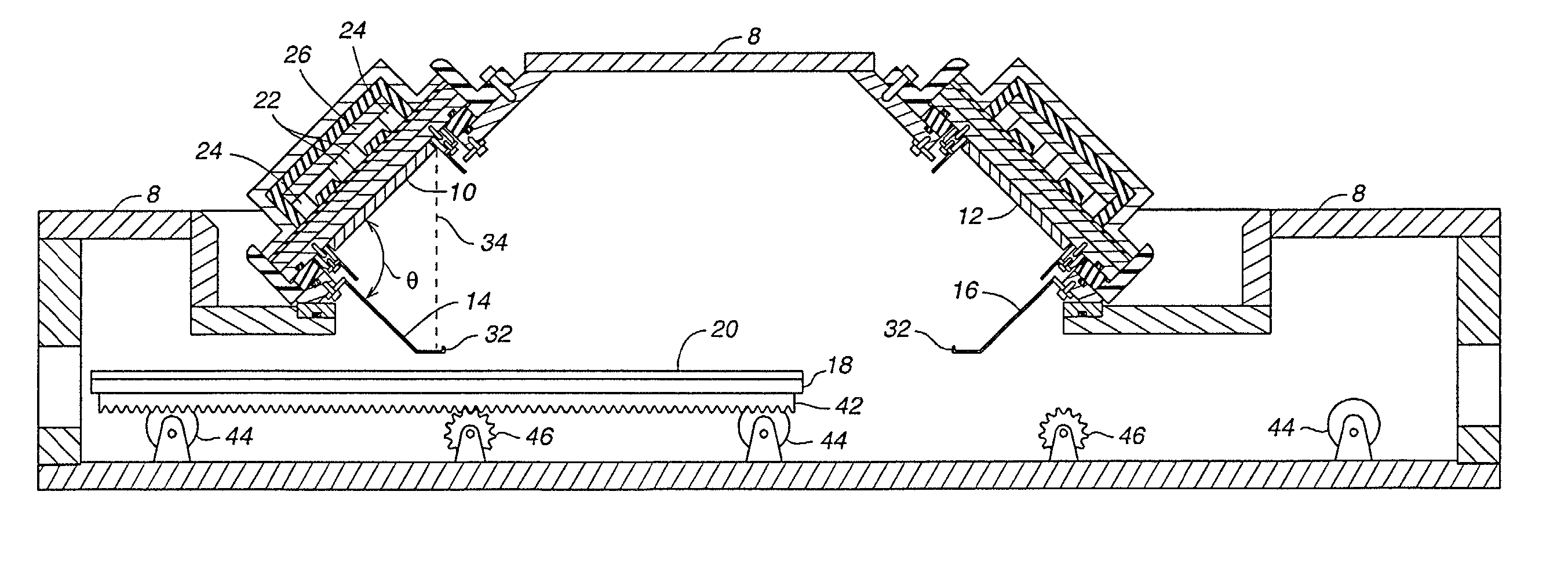
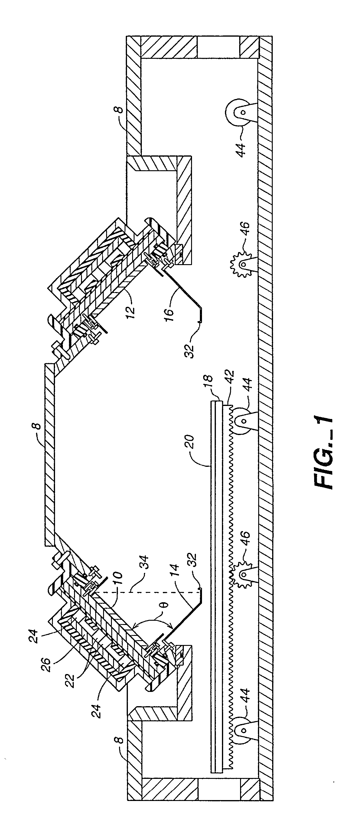
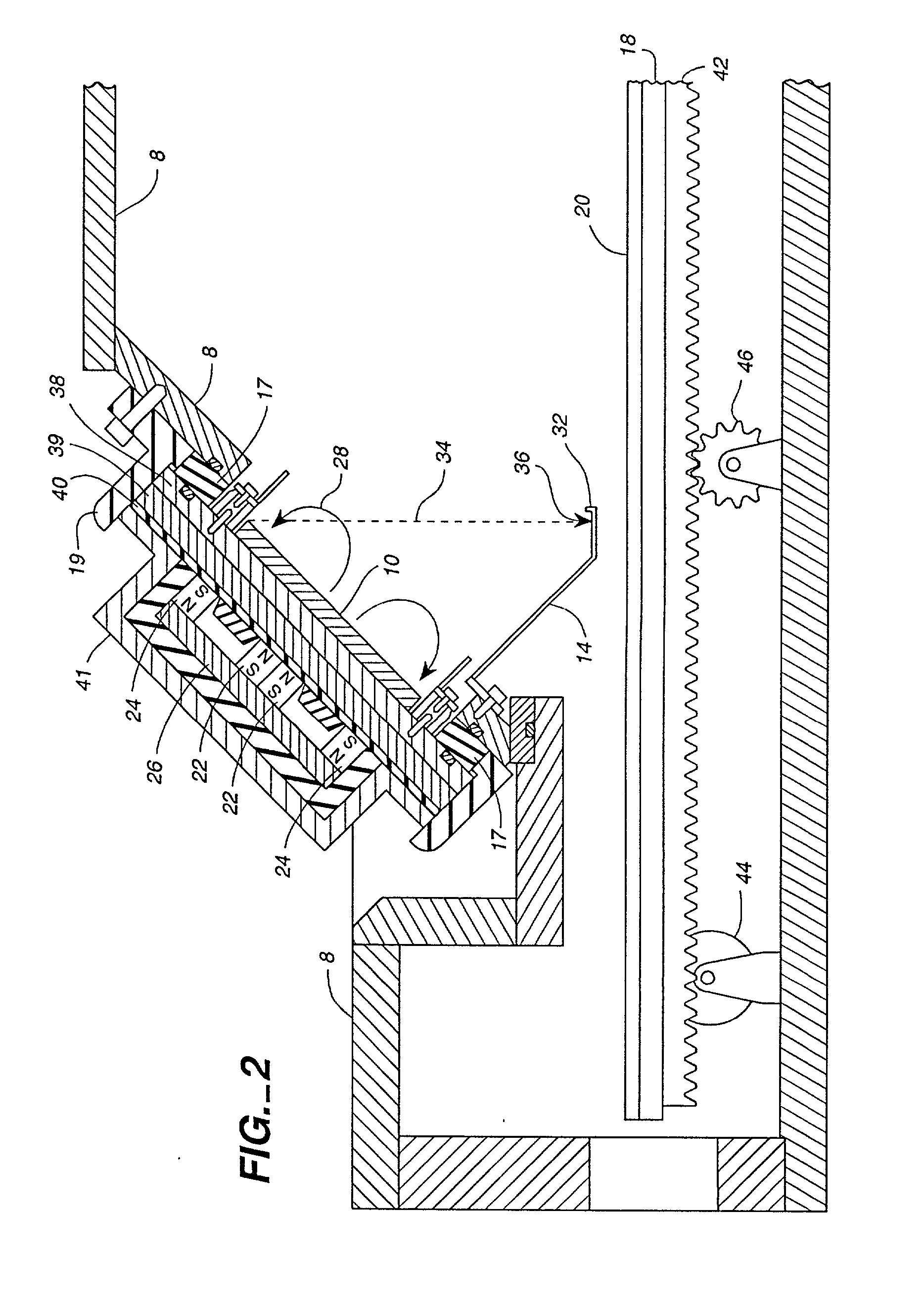
High performance magnetron for DC sputtering systems

a technology of dc sputtering system and magnetron, which is applied in the direction of vacuum evaporation coating, coating, plasma technique, etc., can solve the problems of contaminant particles falling on the workpiece, the electronic device being manufactured, and the most severe corrosion of the workpiece, etc., to achieve mechanical support of a large glass substrate in a vertical orientation without excessive stress and even cracking the substra

Inactive Publication Date: 2002-04-25
APPLIED MATERIALS INC
View PDF0 Cites 45 Cited by
  • Summary
  • Abstract
  • Description
  • Claims
  • Application Information

AI Technical Summary

Problems solved by technology

Some types of commonly used target material tend to produce particles of contaminants that can ruin the electronic device being manufactured if the particles fall on the workpiece.
The problem of contaminant particles falling on the workpiece is most severe when the target and workpiece are both oriented horizontally, with the target directly above the workpiece.
However, it is difficult to mechanically support a large glass substrate in a vertical orientation without excessively stressing and even cracking the substrate.
A further difficulty arises in the utilization factor for both deposition chamber operating time and for target life.
As target bombardment proceeds, gas ion current distribution across the target correlates with magnetic flux density, which typically is non-uniform across the target surface.
Changing tiles in deposition chambers is costly.
Breaking the vacuum to replace tiles involves cooling down the chamber from operating temperatures, replacing the target, re-heating the chamber to bake out water vapor absorbed from ambient air, and burning-in time to remove an oxide layer which inevitably forms on the tiles, all with concomitant energy consumption in the process.
Morrison largely employs solid magnet configurations, however, which aggravate capital cost and complexity and deviate significantly from conventional practices.

Method used


Image

  • High performance magnetron for DC sputtering systems
  • High performance magnetron for DC sputtering systems
  • High performance magnetron for DC sputtering systems

Examples


example

[0068] The configurations depicted in FIGS. 9 and 12 were constructed for a 4300 PVD system and the magnetic flux density measured across target 10 using a 3-axis Hall-effect probe. Magnetic flux proved more widely distributed for the 45.degree. oriented perimeter magnets 124 of the system of FIG. 12 than for the 90.degree. degree oriented perimeter magnets 24 of the system of FIG. 9. Specifically, flux density increased from 100 to 600 gauss in free electron region 129 between inner and outer magnets 22, 124 and attenuated by 50 to 200 gauss in other regions of target 10 where development of grooves 25, 27 was greatest for the 90.degree. system. Further, DC output voltage for the 45.degree. system was 35% lower than for the 90.degree. system for a constant power output level.


PUM

PropertyMeasurementUnit
magnetization angleaaaaaaaaaa
angleaaaaaaaaaa
magnetization anglesaaaaaaaaaa

Abstract

A sputter deposition apparatus and method includes perimeter magnets oriented an angle relative to the plane of the sputter target, either by magnetizing or by physically orienting the magnets at the chosen angle. The resulting magnetic flux extends radially outward, away from the central axis of the target, toward and beyond the target perimeter. This causes the return path of the flux to pass over the target surface more parallel to the plane of its sputtering surface. This spreads sputter erosion over a greater area of the target surface and mitigates development of sputtering grooves. Since target erosion is more uniform, more target material is used for sputter deposition, deterring waste. Each target can be used longer before the target material is penetrated, resulting in fewer target replacement cycles for a given volume of workpiece coating, raising the deposition chamber capacity factor.

Description

[0001] This is a continuation-in-part of Application No. 09 / 429,762, filed Oct. 10, 1999, now pending.[0002] 1. Field of the Invention[0003] The invention relates generally to equipment for performing sputter deposition on an electronic workpiece such as a flat panel display, and particularly to a tilted sputtering target and shield for preventing particles of contaminants from falling from the target onto the workpiece. Still more particularly, this invention relates to an arrangement and orientation of accelerator magnets that improves the efficiency of target material and deposition chamber utilization.[0004] 2. Description of Related Art[0005] Large flat panel displays and other electronic devices generally are manufactured by a series of process steps in which successive layers of material are deposited on a workpiece, such as a glass substrate, and then patterned. Some of the deposition steps typically are performed by sputter deposition, which is deposition by sputtering mate...

Claims


Application Information

Patent Timeline
Patent Type & Authority Applications(United States)
IPC IPC(8): C23C14/34C23C14/00C23C14/35C23C14/56H01J37/32H01J37/34H01L21/203H05H1/46
CPCC23C14/352C23C14/56H01J37/3447H01J37/3408H01J37/3405H01J37/34
Inventor HOSOKAWA, AKIHIROMULLAPUDI, RAVI
Owner APPLIED MATERIALS INC
Why Eureka
Try Eureka