
Modular socket prosthesis

a technology of modular sockets and sockets, applied in the field of modular socket prosthesis, can solve the problems of insufficient anchorage of hourglass connections, insufficient rigidity of bone structure and anchorage, so-called interlocking

Inactive Publication Date: 2002-04-25
THURGAUER KANTONALBANK A CHARTERED IN & EXISTING UNDER THE LAWS OF SWITZERLAND THAT MAINTAINS ITS PRINCIPAL OFFICES AT
View PDF0 Cites 31 Cited by
  • Summary
  • Abstract
  • Description
  • Claims
  • Application Information

AI Technical Summary

Benefits of technology

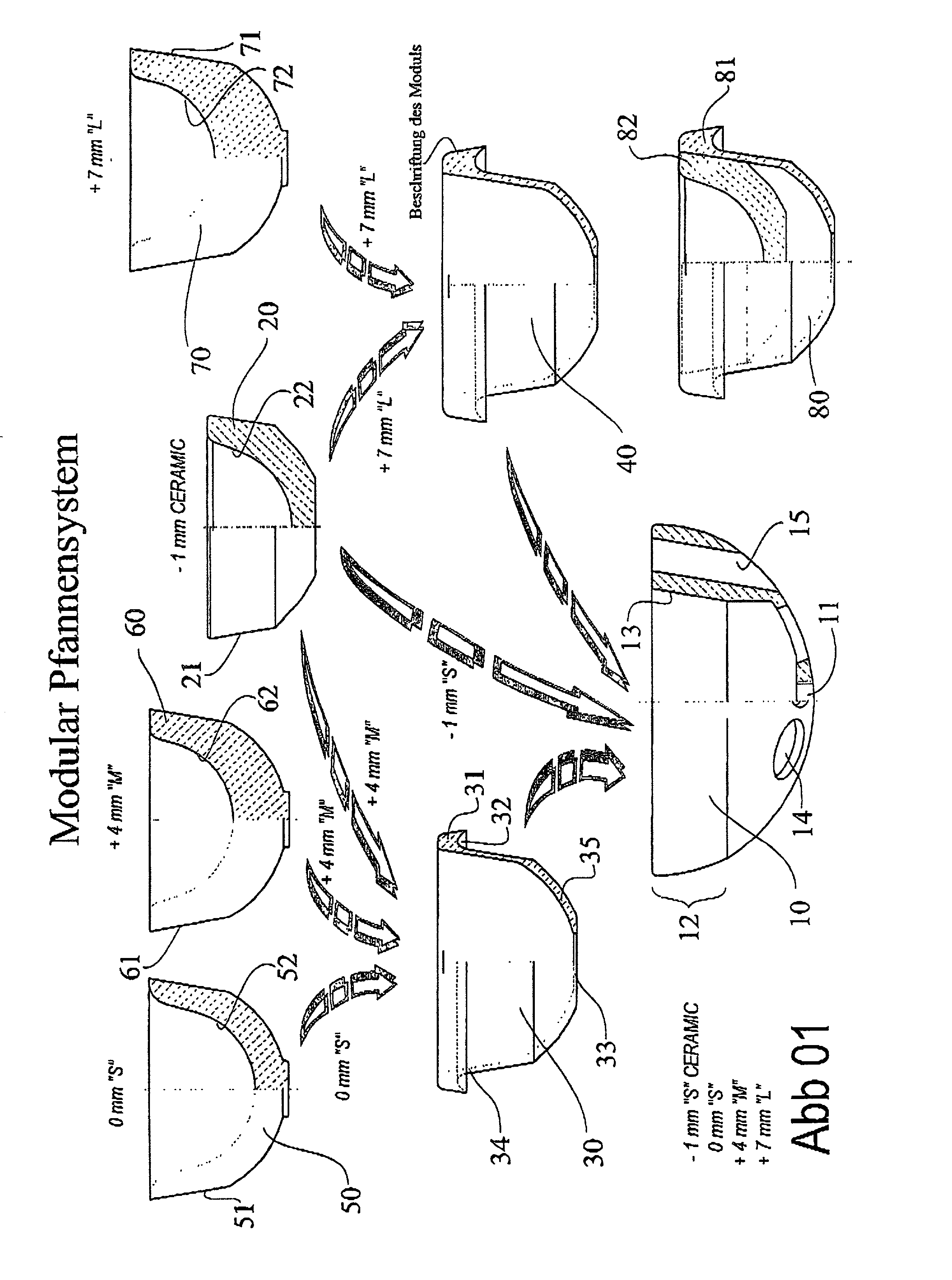
[0012] The shell (FIG. 01 / 10), which in this case is made of titanium, has perforations in its topdome to reduce the mass and to increase the overall elasticity of the design (FIG. 01 / 14). The holes in the wall of the titanium implant (FIG. 01 / 15) have cushioning properties relative to the bone, as can be shown by finite element calculations.
[0014] The module (FIG. 01 / 30) thereby experiences a relative change in the offset of 0 mm relative to the pure ceramic inlet [sic: insert] (FIG. 01 / 20) of -1 mm; and the module (FIG. 01 / 60) may have an offset of +4 mm. The offset in a socket refers to the distance from the median plane to the center of rotation, and it is inherent in this definition that the topography of the physiological center rotation is defined as a 0 mm. A module having an offset of +7 mm has also been designed, as shown in FIG. 01 / 40. The module may be constructed of a single piece and it may be rigidly attached with components made of ceramic, HDPE, metal, or some other abrasion-resistant material, which would be advantageous.
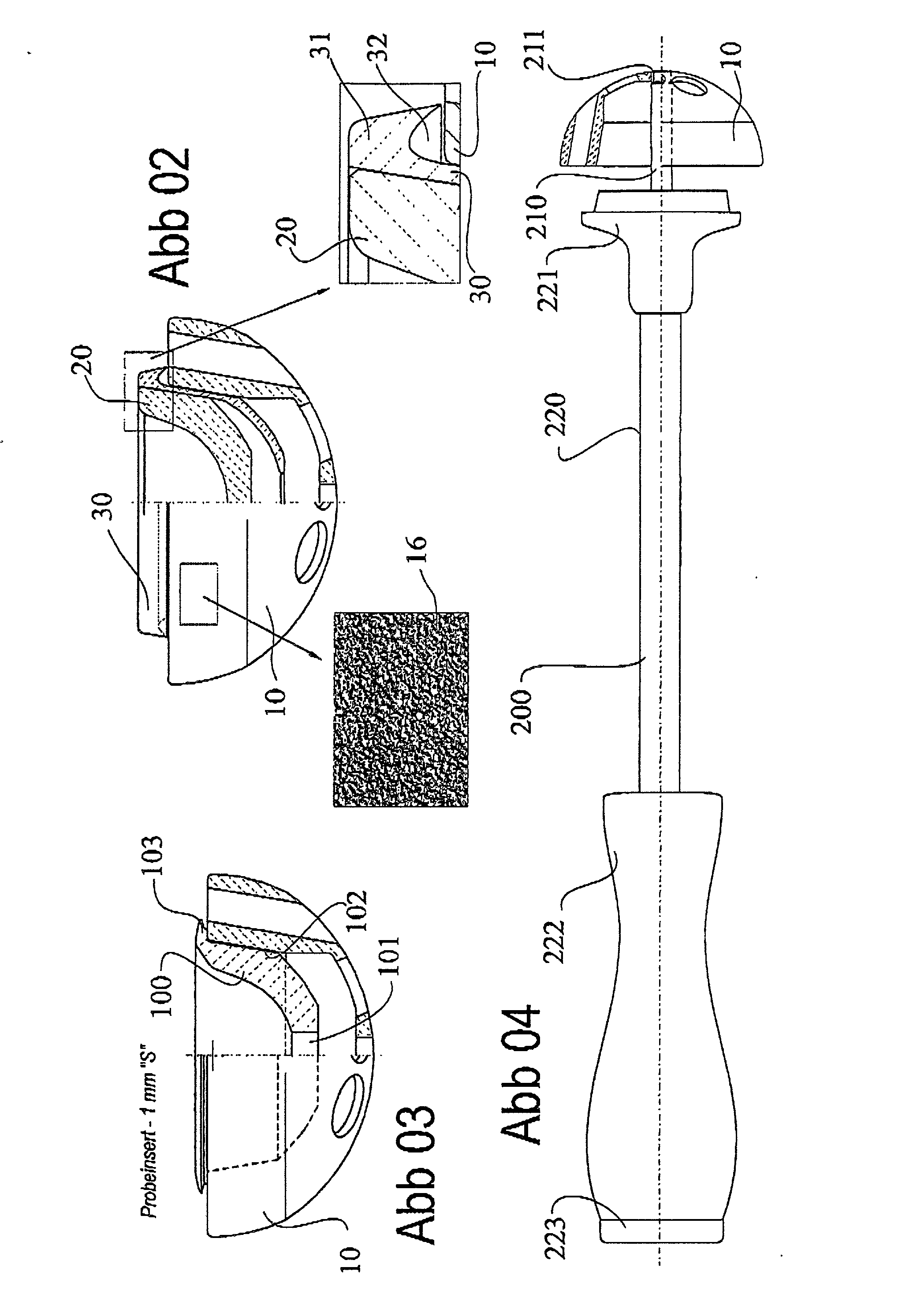
[0019] The base of the trial insert has an opening (FIG. 03 / 101). The support surface (FIG. 03 / 102) has a conical shape that corresponds to the socket shell, and the support around the circumference of the shell is in the form of a large lip (FIG. 03 / 103). The trial insert can be easily removed.

Problems solved by technology

The plastic socket is cemented onto a relatively dense bone, which means that the bone cement cannot penetrate at all into the bone if no anchorage holes have been made.
Such anchorage holes, however, represent hourglass connections that do not provide sufficient anchorage since the spongiosa structure in the acetabulum initially has a closely spaced honeycomb, which becomes more widely spaced as one moves in the proximal direction toward the spinal column / pelvis connection.
Filling occurs "against" the morphological structure, and as a result both the rigidification of the bone structure as well as the anchorage--the so-called interlocking--is inadequate.
However, the screw threads result in bone necrosis and pelvis fractures.
Combining this approach with a threaded connection also failed to solve the problem.
But in any event it means that the leg as a whole is medialized further, which can result in pelvitrochanterian insufficiency.
This means that the muscles become relatively long and have an unfavorable lever arm.

Method used


Image

  • Modular socket prosthesis
  • Modular socket prosthesis
  • Modular socket prosthesis

Examples


example

[0017] A patient having advanced coxarthrosis is positioned on the operating table in the usual manner and, after the surgical area has been covered and prepared using sterile techniques, the hip joint is exposed, for example by means of a lateral access, the capsule is opened, the femur is dislocated, and the head of the femur is removed and lifted away. Following this, the hip socket is adjusted and the cartilage is removed using a sharp ruffle fluted cutter.

[0018] As soon as the bone has been exposed, the fluted cutter is replaced with a diamond cutter and, using the same size as the head, the bed is ground open spherically. The next larger size diamond grinder is used to cut down to the bottom of the socket until the edge of the spherical hollow grinding tool disappears into the socket. A titanium shell is now screwed on to the setting instrument (FIG. 04), and the setting instrument is positioned in the ground-out bed of the socket and is hammered into place in the bone bed in ...


PUM


Abstract

The present invention essentially relates to a hip joint socket system for a "press-fit" anchorage in the bony acetabulum that allows the inserts that articulate with the artificial head to be connected securely, and, using said inserts, also allows the center of the rotation of the socket to be reconstructed, the risk of luxation to be eliminated, and the plane of load application to be varied across an infinite range of positions within a defined angular range.

Description

[0001] The success of the permanent anchorage of hip joint components is linked to the publications by Sir John Charnley, who cemented the components into place using bone cement, such as the publication that appeared in the Journal of Bone and Joint Surgery: Charnley. J., (1960), Anchorage of the Femoral Head Prosthesis to the Shaft of the Femur JBJSB 42: 28-30. The combination of the cemented plastic socket also goes back to J. Charnley (Low Friction Arthroplasty of the Hip: Theory and Practice, Heidelberg, N.Y., Berlin: Springer. However, combination with plastic resulted in unexpectedly high wear.[0002] Therefore, researchers attempted to find combinations for the articulation that could be expected to have low wear. Industrial experience told them that the smoothest surfaces could be achieved with ceramics. The articulation of ceramic against ceramic currently allows one to expect wear that will be 200 times less than that with a polyethylene-metal head. However, such an articu...

Claims


Application Information

Patent Timeline
Patent Type & Authority Applications(United States)
IPC IPC(8): A61F2/00A61F2/30A61F2/32A61F2/34A61F2/46
CPCA61F2002/30324A61F2002/30014A61F2002/30542A61F2002/30563A61F2002/30713A61F2002/30787A61F2002/3233A61F2002/3401A61F2002/3403A61F2002/3404A61F2002/3429A61F2002/3456A61F2002/3459A61F2002/3469A61F2002/4623A61F2002/4681A61F2220/0033A61F2250/0018A61F2250/0036A61F2250/0087A61F2310/00017A61F2310/00023A61F2310/00029A61F2310/00131A61F2310/00179A61F2/34A61F2/4609A61F2/4684A61F2002/30332A61F2002/3054A61F2002/3071A61F2/4603
Inventor DRAENERT, KLAUS
Owner THURGAUER KANTONALBANK A CHARTERED IN & EXISTING UNDER THE LAWS OF SWITZERLAND THAT MAINTAINS ITS PRINCIPAL OFFICES AT
Learn More