
Multiple beams and nozzles to increase deposition rate

Inactive Publication Date: 2002-05-02
OPTOMEC DESIGN CO
View PDF1 Cites 29 Cited by
  • Summary
  • Abstract
  • Description
  • Claims
  • Application Information

AI Technical Summary

Problems solved by technology

Experience has shown, however, that this nozzle design does not provide uniform flow independent of the translation direction.
In addition, to achieve goal material properties, the deposition rate is sufficiently low, such that fabrication times required for even intermediate volume objects (100 cubic inches) are prohibitive.
This design provides a unique method for coating parts; however, it has never been intended for fabrication of multilayered parts.
Due to the diverging nature of the powder material, this plasma technique fails to provide the feature definition necessary for fabricating complex, net-shaped objects.
For a single laser beam that is coaxial to the powder flow, this nozzle should work well to provide a uniform layer; however, there is concern that the powder distribution at the deposition surface is greatest at the center of the deposition region, causing it to diminish radially away from the center of the deposition spot.
However, this reduces the rate of deposition and increases the time to produce parts.
Furthermore, expitaxial growth is not desired in most three-dimensional parts, since it may result in anisotropic material characteristics.
The above single laser nozzle's side design lack the ability to increase the deposition rate of powder without sacrificing vital process conditions, including reduced residual stress, enhanced material properties, process time, and good dimensional repeatability, as well as feature definition.
Also, this nozzle design does not provide uniform flow independent of the translation direction.
Therefore, such nozzle designs are not suitable for mass 3-D net-shape production.
However, this patent only uses a single laser beam for the deposition process, which uses wire as the feedstock material.
Such a continuous form of material would appear to be prone to substantial problems of warpage and distortion of the deposited layers due to an incomplete melting of the feedstock material.

Method used


Image

  • Multiple beams and nozzles to increase deposition rate
  • Multiple beams and nozzles to increase deposition rate
  • Multiple beams and nozzles to increase deposition rate

Examples


Embodiment Construction

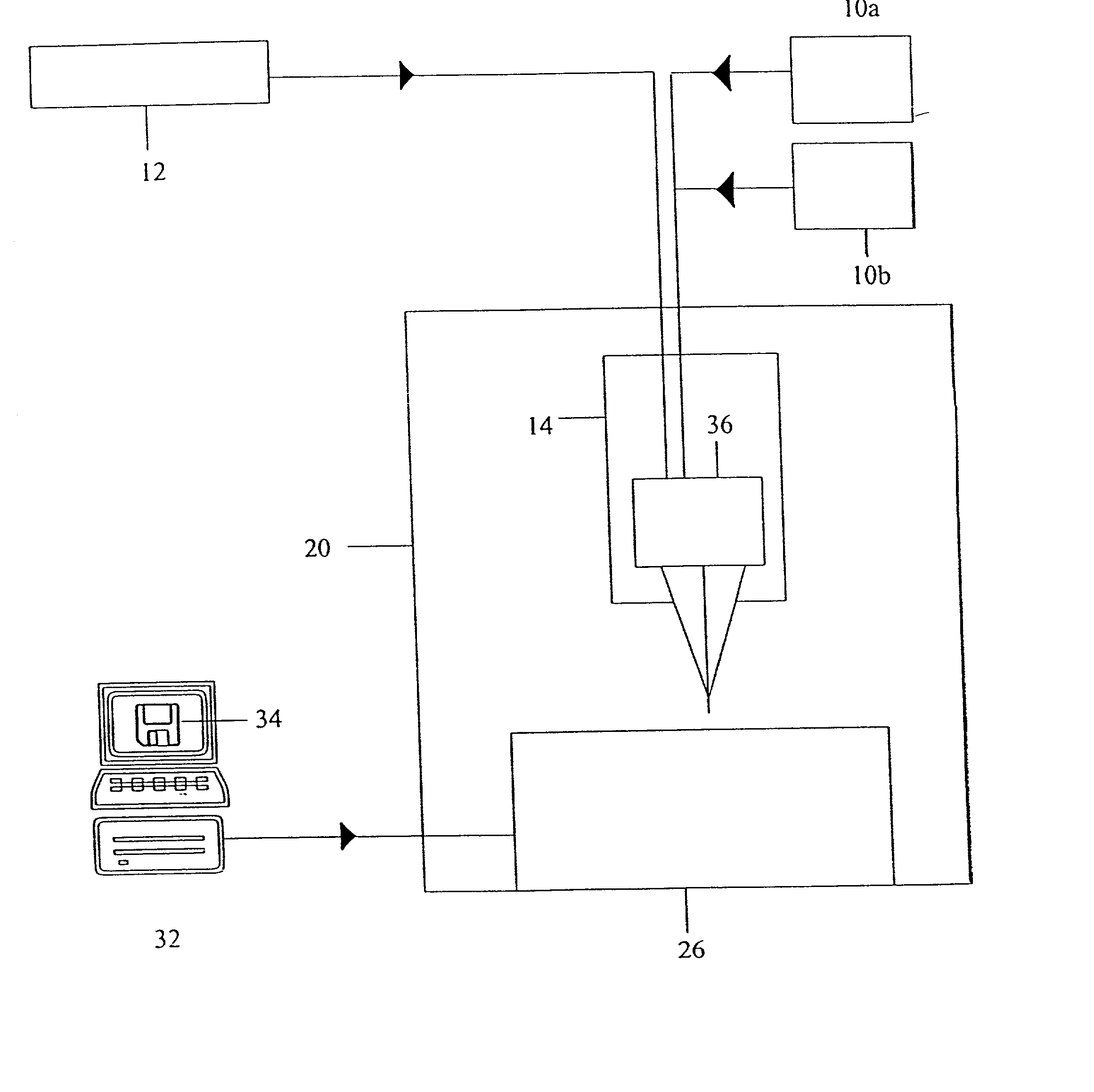
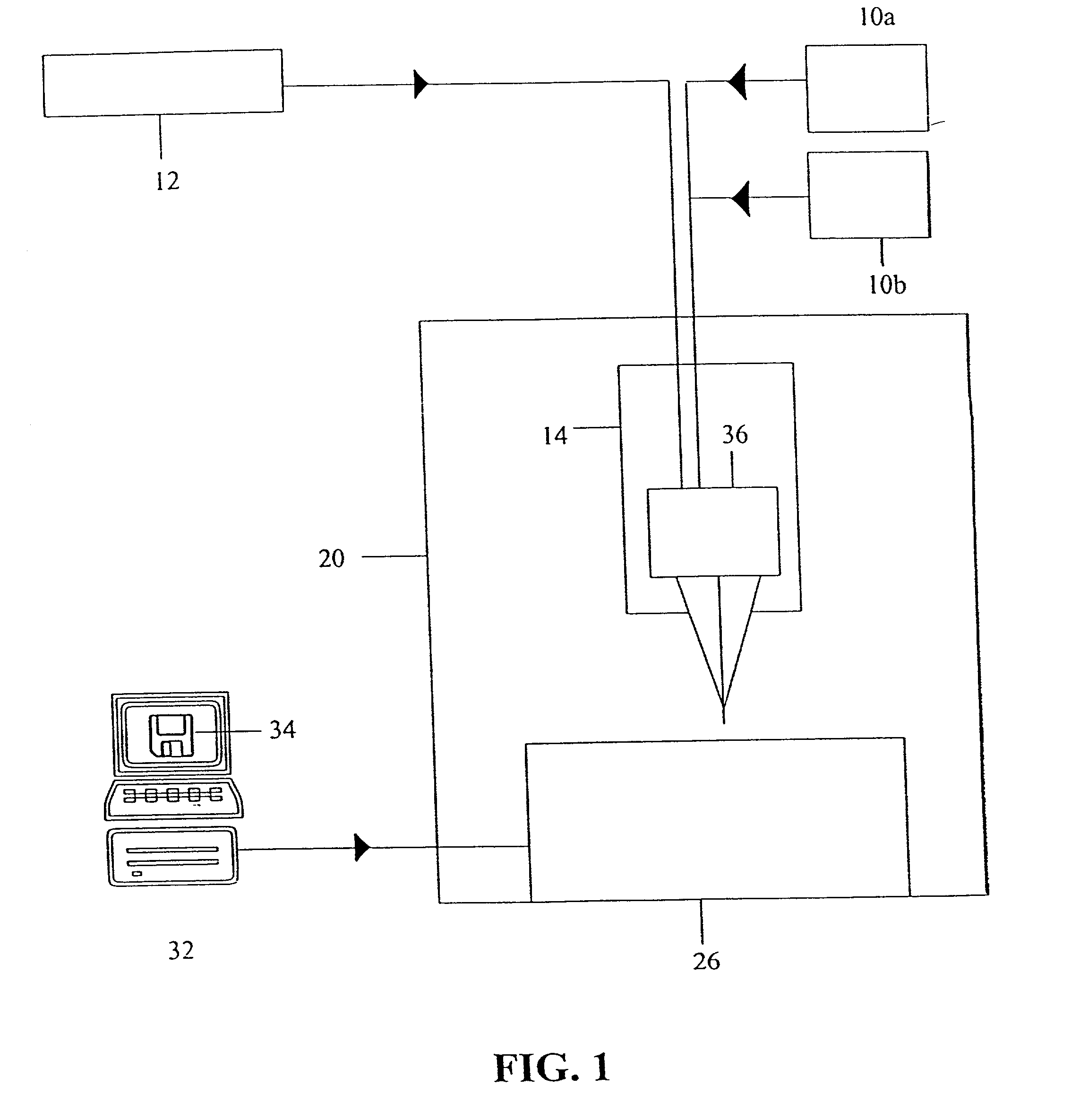
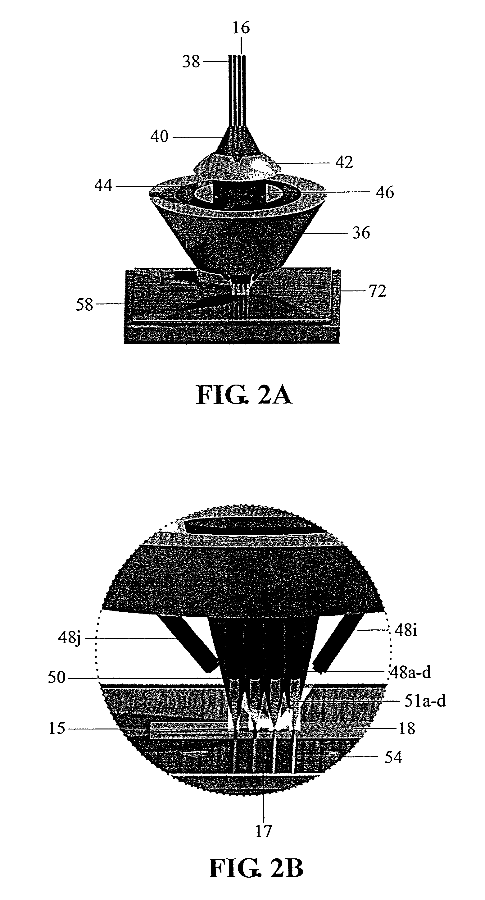
[0043] This invention can be explained in terms of the multiple nozzle deposition apparatus and the multiple laser beam deposition apparatus. The multiple nozzle deposition apparatus has been developed for the application of powdered materials onto a substrate to create a uniform fused layer in a desired pattern with exceptional material properties, very good dimensional accuracy, and at a rate that is practical for the direct fabrication of solid objects. In the preferred embodiment, four beam delivery fibers 38 transmit approximately equally powered laser beams that become four focused laser beams 50 that are used as heat sources to melt the powder supplied to the deposition region, where it is fused to the deposition substrate 58, as shown in FIGS. 2A, 2B, and 6. For this invention, the number of focused laser beams 50 is not nearly as important as the concept of using multiple beams to achieve normally conflicting requirements of a high deposition rate coupled with exceptional m...


PUM

PropertyMeasurementUnit
Material propertiesaaaaaaaaaa

Abstract

A method has been developed to exploit the desirable material and process characteristics provided by a low powered laser material deposition system, while overcoming the low material deposition rate imposed by the same process. One application of particular importance for this invention is direct fabrication of functional, solid objects from a CAD solid model This method of fabrication uses a software interpreter to electronically slice the CAD model into thin horizontal layers that are subsequently used to drive the deposition apparatus. The apparatus uses a single laser beam to outline the features of the solid object and then uses a series of equally spaced laser beams to quickly fill in the featureless regions. Using the lower powered laser provides the ability to create a part that is very accurate, with material properties that meet or exceed that of a conventionally processed and annealed specimen of similar composition. At the same time, using the multiple laser beams to fill in the featureless areas allows the fabrication process time to be significantly reduced.

Description

[0001] This is a division of Ser. No. 09 / 010,673, Filed Jan. 22, 1998.[0002] 1. Field of Invention[0003] This invention relates to the use of multiple beams and nozzles in direct material deposition (DMD) processes in order to increase the deposition rate without compromising material properties or dimensional accuracy.[0004] 2. Description of Prior Art[0005] Direct material deposition processes allow complex components to be efficiently fabricated in small lot sizes to meet the stringent requirements of the rapidly changing manufacturing environment. This process produces three-dimensional parts directly from a computer aided design (CAD) solid model. U.S. Pat. No. 4,323,756 teaches that complex, net-shaped objects can be built by sequential layer deposition of feedstock material in powder or wire form, whereby the material is directed into a focused laser beam, melted, and deposited onto a deposition substrate to generate solid objects of varying three-dimensional complexity in a ...

Claims


Application Information

Patent Timeline
IPC IPC(8): B23K26/14B29C67/00
CPCB23K26/1411B29C67/0092B29C67/0077B23K26/144B29C64/153B29C64/40
Inventor KEICHER, DAVID M.MILLER, W. DOYLE
Owner OPTOMEC DESIGN CO
Learn More