Valve timing control system for internal combustion engine

a timing control and internal combustion engine technology, applied in the direction of electric control, ignition automatic control, machines/engines, etc., can solve the problems of insufficient temperature increase and quality improvement of exhaust gas, and achieve the effect of improving the performance of the internal combustion engine in the ordinary operation mod

Inactive Publication Date: 2002-05-30
MITSUBISHI ELECTRIC CORP +1
View PDF0 Cites 11 Cited by
  • Summary
  • Abstract
  • Description
  • Claims
  • Application Information

AI Technical Summary

Benefits of technology

0113] With the arrangement of the valve timing control system described above, performance of the internal combustion engine in the ordinary operation modes can considerably be improved to another advantage.

Problems solved by technology

To say in another way, the conventional valve timing control system suffers problems that the catalyst temperature can not sufficiently be increased and that the quality of the exhaust gas yet remains to be improved.

Method used


Image

  • Valve timing control system for internal combustion engine
  • Valve timing control system for internal combustion engine
  • Valve timing control system for internal combustion engine

Examples


embodiment 1

[0131] In the following, a valve timing control system for an internal combustion engine according to a first embodiment of the present invention will be described in detail by reference to the drawings.

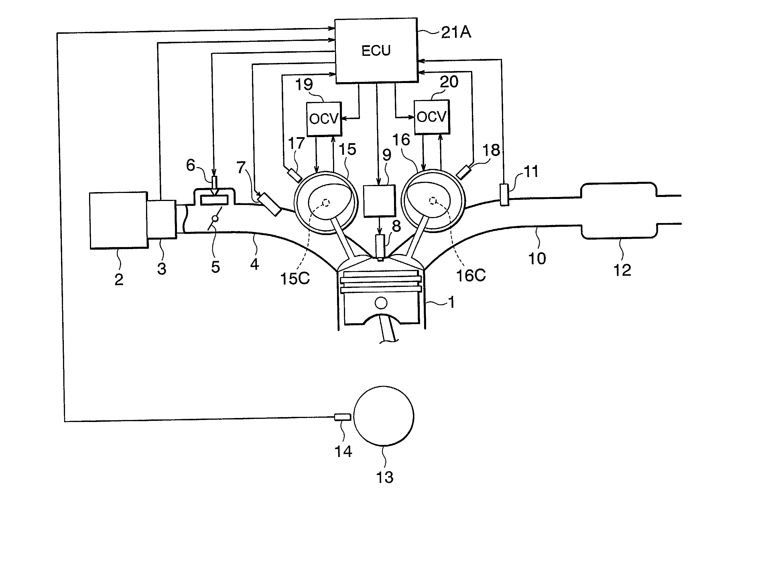
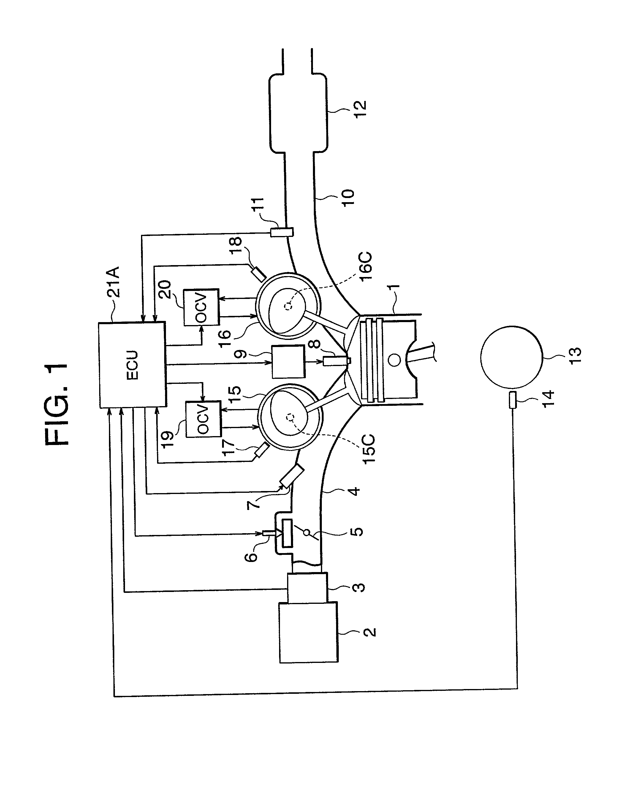
[0132] FIG. 1 is a schematic block diagram showing generally a configuration of the valve timing control system for the internal combustion engine according to the first embodiment of the invention. In the figure, components same as or equivalent to those mentioned hereinbefore by reference to FIG. 6 are denoted by like reference characters as those used in this figure and detailed description thereof is omitted.

[0133] Accordingly, in the valve timing control system for the internal combustion engine according to the instant embodiment of the invention, the change control range of the valve timings for the intake valve and the exhaust valve is essentially same as shown in FIG. 7, and the relation between the output of the crank angle sensor and that of the cam angle sensor is also sa...

embodiment 2

[0174] In the case of the valve timing control system for the internal combustion engine according to the first embodiment of the invention, the temperature rise of the catalyst 12 and the accelerated purification of the exhaust gas are realized through the valve timing advancing control performed with the aid of the actuators 15 and 16 in the cold-state idling operation mode of the engine 1. It should however be noted that in addition to such valve timing advancing control, the ignition timing of the engine 1 may be so controlled as to be retarded.

[0175] In the following, description will be directed to the valve timing control system for the internal combustion engine according to a second embodiment of the present invention, which system is designed to control the ignition timing of the engine 1 so that it is retarded in the idling operation carried out in the engine 1 in the cold state thereof.

[0176] FIG. 3 is a flow chart for illustrating control operation of the valve timing c...

embodiment 3

[0182] In the case of the valve timing control system for the internal combustion engine according to the second embodiment of the invention, the ignition timing of the engine is so controlled as to be retarded in addition to the advancing control of the actuators 15 and 16 in the idling operation of the engine 1 in the cold state thereof. It is however to be noted that the quantity of fuel supplied to the cylinders of the engine 1 may also be so controlled as to be decreased substantially to the similar effect. A third embodiment of the present invention concerns the valve timing control system in which the injection fuel quantity decreasing control is adopted.

[0183] In the following, description will be directed to the valve timing control system for the internal combustion engine according to a third embodiment of the present invention, which system is designed to perform the fuel injection quantity decreasing perform in the cold-state idling operation mode of the engine 1.

[0184]...


PUM


Abstract

A valve timing control system for accelerating activation of a catalytic converter in an internal combustion engine in a cold starting operation mode. The system includes actuators (15, 16) coupled to cam shafts (15C, 16C), hydraulic pressure supply units (19, 20) for driving the actuators (15; 16), and a controller (21A) for controlling a hydraulic pressure for the actuators (15, 16) in dependence on engine operation states to change phase of the cam shafts (15C; 16C) relative to a crank shaft. The actuator (15; 16) includes a locking mechanism (155, 157) for setting the relative phase to a lock-up position, and an unlocking mechanism (156) for releasing the locking mechanism in response to a predetermined hydraulic pressure. The controller (21A) sets the relative phase to the lock-up position in a starting operation, while controlling the relative phase to be advanced in an engine state succeeding to the starting operation.

Description

BACKGROUND OF THE INVENTION[0001] 1. Field of the Invention[0002] The present invention relates in general terms to a valve timing control system for an internal combustion engine for controlling operation timings of intake valves and exhaust valves of the engine in dependence on engine operating states. More particularly, the present invention is concerned with a valve timing control system for an internal combustion engine which system is designed for promoting temperature-rise (or temperature-up) of a catalytic converter disposed in an exhaust pipe of the engine for realizing a significant reduction of harmful exhaust gas components discharged from the engine by controlling the valve timing toward an advanced phase or state during idling operation of the engine in a cold engine state (i.e., engine state of a low temperature).[0003] 2. Description of Related Art[0004] In recent years, the statutory regulations imposed in connection with emission of harmful materials or substances ...

Claims


Application Information

Patent Timeline
Patent Type & Authority Applications(United States)
IPC IPC(8): F01L1/34F01L1/344F01L13/00F02D13/02F02D41/00F02D41/02F02D41/06F02P5/15
CPCF01L1/022Y02T10/26F01L1/34F01L1/3442F01L2001/0537F01L2001/3443F01L2001/34473F01L2800/00F01L2820/041F01N2430/10F02B2275/18F02D13/0219F02D13/0261F02D41/0255F02D41/064F02D2013/0292F02D2041/001F02D2041/002F02P5/1506Y02T10/46Y02T10/18F01L1/024Y02T10/12Y02T10/40
Inventor TAKAHASHI, TATSUHIKOHASHIMOTO, ATSUKOOHUCHI, HIROFUMI
Owner MITSUBISHI ELECTRIC CORP
Why Eureka
Try Eureka