
Miniature X-ray tube constructions

a technology of x-ray tube and construction, which is applied in the field of x-ray tube, can solve the problems of renarrowing of the vessel, aggravate restenosis, and increase hyperplasia, and achieve the effect of increasing heat dissipation

Inactive Publication Date: 2002-05-30
MEDIRAD I R T
View PDF0 Cites 33 Cited by
  • Summary
  • Abstract
  • Description
  • Claims
  • Application Information

AI Technical Summary

Benefits of technology

[0010] One object of the present invention is to provide an X-ray tube of an improved miniaturized construction, particularly useful for many therapeutic and / or diagnostic medical applications, but which can also be used in many industrial applications, such as in the non-destructive testing of parts. Another object of the invention is to provide an X-ray tube of a construction which includes cooling to increase heat dissipation, but which still can be constructed in relatively miniaturized form for many therapeutic, diagnostic and industrial applications. A further object of the invention is to provide an X-ray tube, of a construction which includes a cold cathode providing a high-intensity source of field-emission electrons making the X-ray tube particularly suitable for medical applications.
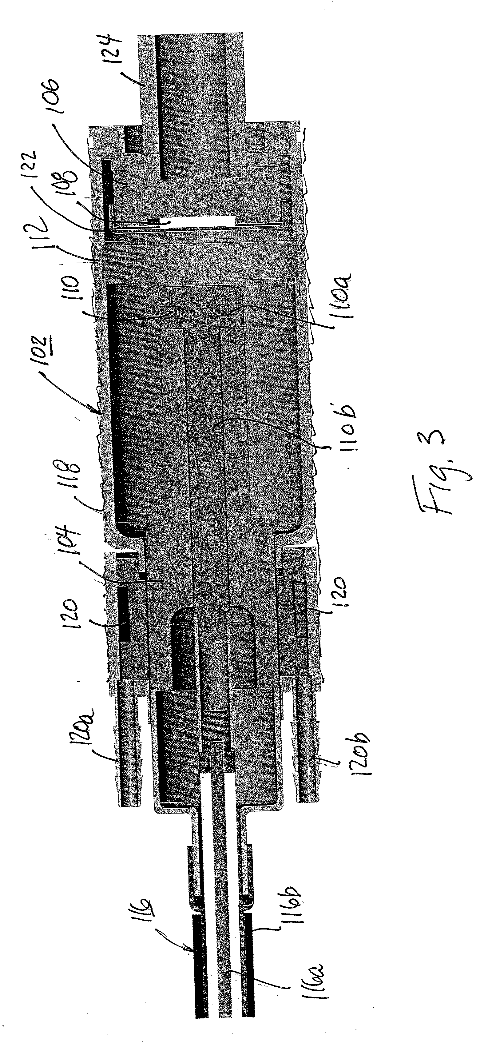
[0012] Such a construction, permitting external cooling of the tube, provides for a higher rate of heat dissipation, and thereby enables such miniaturized X-ray tubes to be used in many applications, particularly medical applications, requiring higher tube outputs without excessive heating.

Problems solved by technology

However, such a PCR treatment frequently results in a renarrowing of the vessel, called "restenosis", triggered by the injury to the vessel wall.
It has been found, however, that the placement of a stent may actually increase hyperplasia and thereby aggravate restenosis, rather than reduce it.
Moreover, restenosis following stenting is particularly difficult to treat.
Another technique now being investigated for preventing renarrowing of the vessel caused by hyperplasia is by the use of drugs, but this approach introduces other problems relating to the drug used.
However, external beam radiation, administered in relatively high doses, has a damaging effect on the patient's body, and therefore this approach does not appear to be suitable for reducing restenosis.
The power required, and the heat generated by such an X-ray emitter, would appear to significantly limit its suitability for use against restenosis following PCR.
However, the constructions illustrated in those patents would appear to present substantial difficulties in commercial production using existing vacuum-tube manufacturing technology.
This limits the maximum tube output without excessive heating, which is a serious drawback in their use for medical applications.
Other cold cathode miniature X-ray tube constructions are described in U.S. Pat. Nos. 3,714,486 and 5,729,583, but such constructions are also not particularly suitable for medical applications of the type described above.

Method used


Image

  • Miniature X-ray tube constructions
  • Miniature X-ray tube constructions
  • Miniature X-ray tube constructions

Examples


Embodiment Construction

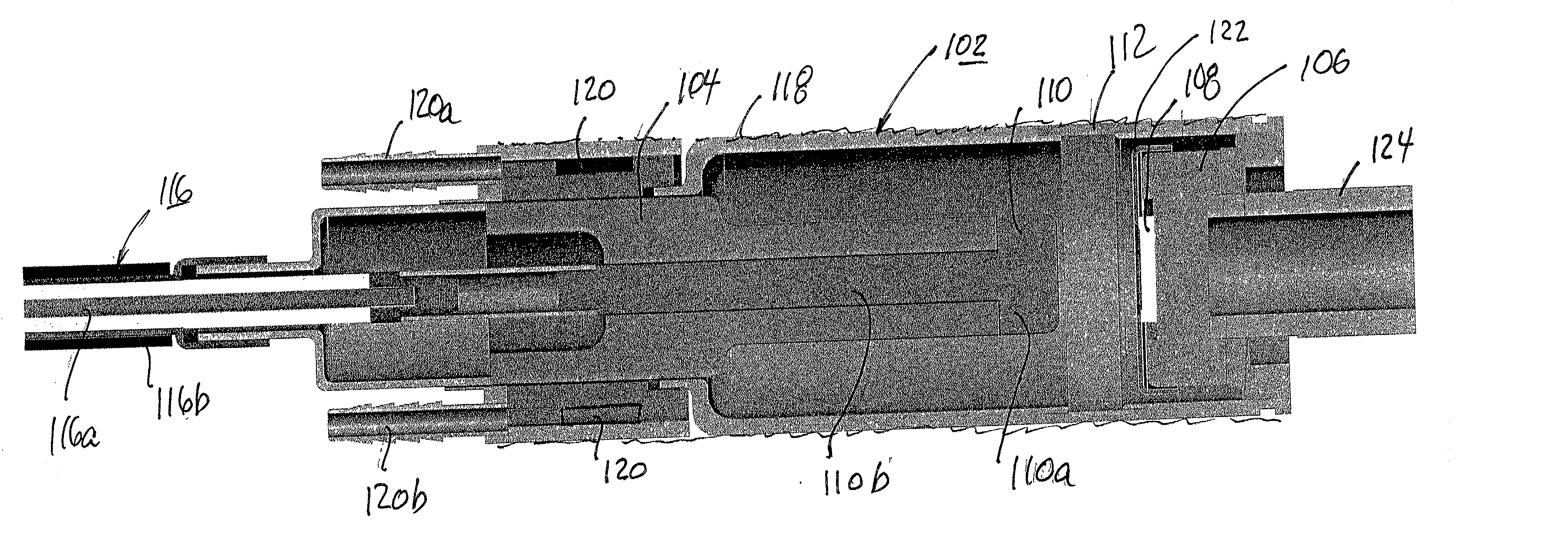
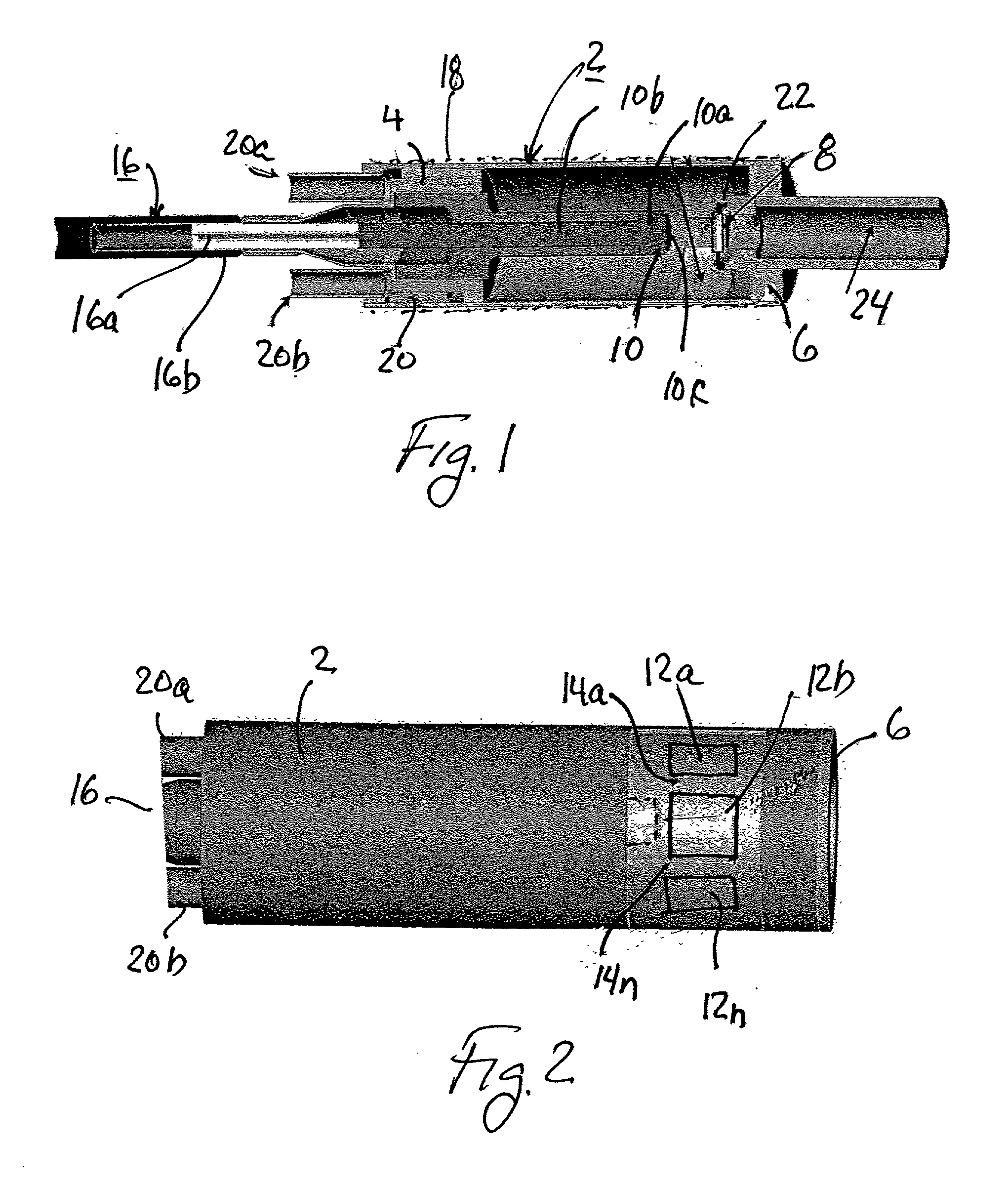
[0024] The X-ray Tube of FIGS. 1 and 2

[0025] The X-ray tube illustrated in FIG. 1 comprises an evacuated envelope constituted of a cylindrical sleeve 2 closed at one end by an end wall 4 sealingly bonded to the tube 2, and at the opposite end by another end wall 6 also sealingly bonded to the tube 2. Sleeve 2 and the two end walls 4, 6 are each made of ceramic material. The ceramic material used for end wall 4 is thermally-conductive, and that used for end wall 6 is electrically-conductive, as will be described more particularly below.

[0026] Ceramic end wall 6 mounts a cold cathode 8 which is capable of field emission of electrons when subjected to a high electrostatic field. Ceramic end wall 4 mounts an anode 10 coaxial with, and axially spaced from, the cathode 8. Anode 10 is made of a material, such as tungsten, capable of emitting X-rays when struck by electrons emitted by the cathode.

[0027] As shown in FIG. 2, envelope 2 includes a plurality of X-ray transparent windows 12a, 12...


PUM


Abstract

An X-ray tube includes an evacuated envelope; a cold cathode mounted at one end of the envelope and capable of field emission of electrons when subjected to a high electrostatic field; and an anode mounted at the opposite end of the envelope coaxial with and axially spaced from the cathode, and capable of emitting X-rays when struck by electrons emitted by the cathode. The envelope includes an end wall made of thermally-conductive and electrically-insulating material in contact with the anode and formed with a fluid cooling channel to remove the heat generated at the anode. In one described embodiment, the cathode includes a body of a getter material which is both electron emissive and gas absorptive. In other described embodiments, the cathode includes a carbon nanotube field-emission electron source.

Description

FIELD AND BACKGROUND OF THE INVENTION[0001] The present invention relates to X-ray tubes, and particularly to X-ray tubes of a miniature construction enabling them to be used in various medical applications, including treating restenosis in blood vessels, cancer therapy, imaging of small body parts, and the like. The invention is particularly useful in coronary revascularization therapy to remove vascular obstructions, and is therefore described below with respect to such application, but may also be used in many other medical applications like radiation therapy of cancers of various cancers as those in gastro-enterology, colorectal and intestines, gynecology and radiation therapy during surgery, as well as in various industrial applications such as in non-destructive testing of parts.[0002] As described in my prior Patent Applications Ser. No. 09 / 414,853, filed Oct. 12, 1999, and Ser. No. 09 / 494,043 filed Jan. 31, 2000, the contents of which are hereby incorporated by reference, co...

Claims


Application Information

Patent Timeline
Patent Type & Authority Applications(United States)
IPC IPC(8): A61N5/10H01J35/32
CPCA61N5/1001A61N5/1002B82Y10/00H01J35/32H01J2235/205H01J2235/1204H01J2235/1262H01J2235/164H01J2201/30469
Inventor KEREN, HANAN
Owner MEDIRAD I R T
Learn More