[0022] The net effect of the invention is to allow a relatively small rotatable filter within a rotary filtration device to act as a much larger size, thus allowing
cost effectiveness and even more important allowing the rotary filter
metal to
metal seals to work in flow conditions where they were previously impractable due to the increased filter areas provided by wave bottom filter supports and filter media.
[0023] It is worth while to examine the factors that make the wave bottom filter possible. The drilling of closely spaced holes through a sharply angled surface will cause the
drill to deflect as it enters or exits on the angled surface. If the holes are deep (ie they have a large length to
diameter ratio expressed as L / D) the normal use of end mills or of
drill collars will not prevent this
distortion. As a result holes have to be drilled in a thick support plate with parallel surfaces, then shaped into a
wave form. If the desired final shape of the hole containing filter support is a rectangular plate there would be no problem in fabrication of
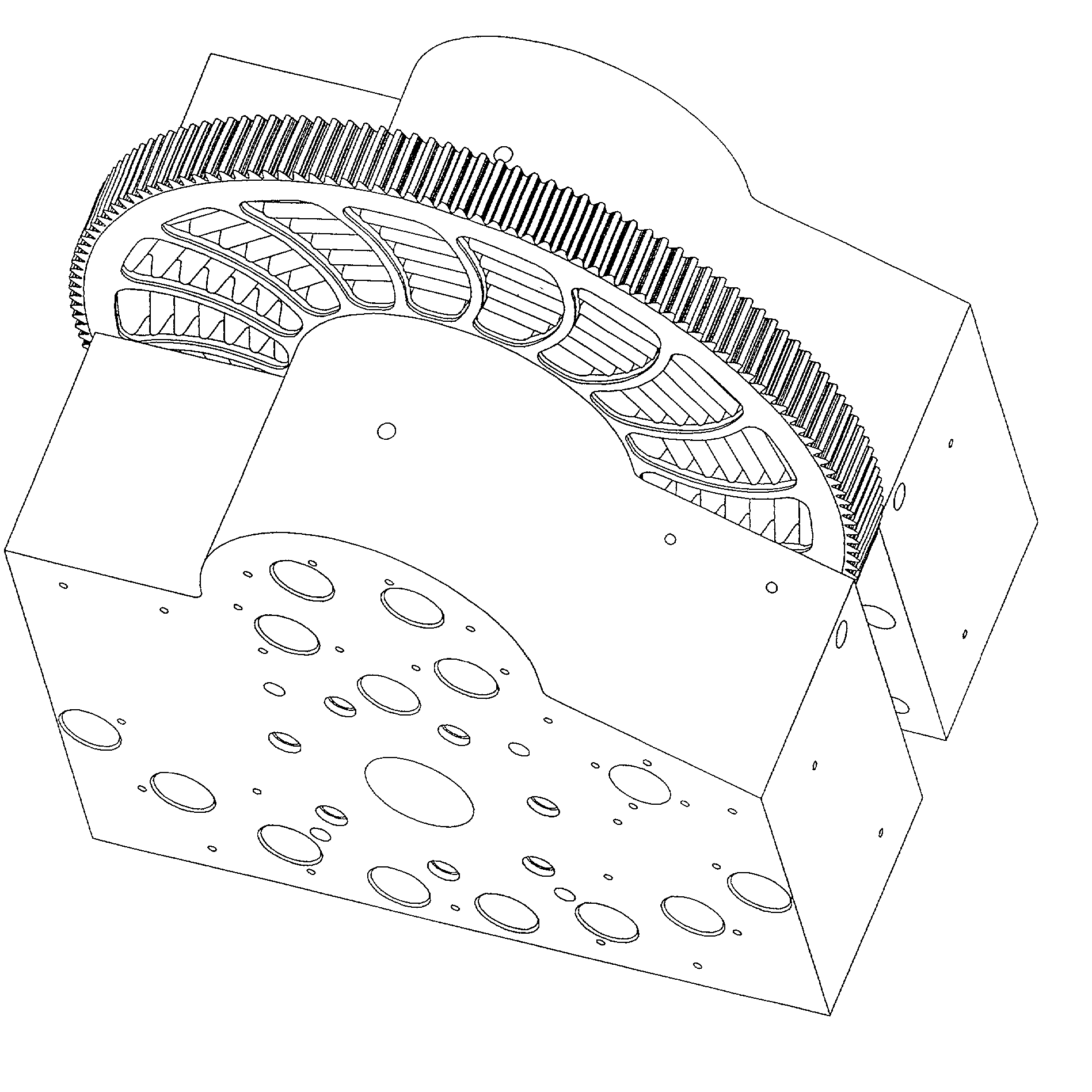
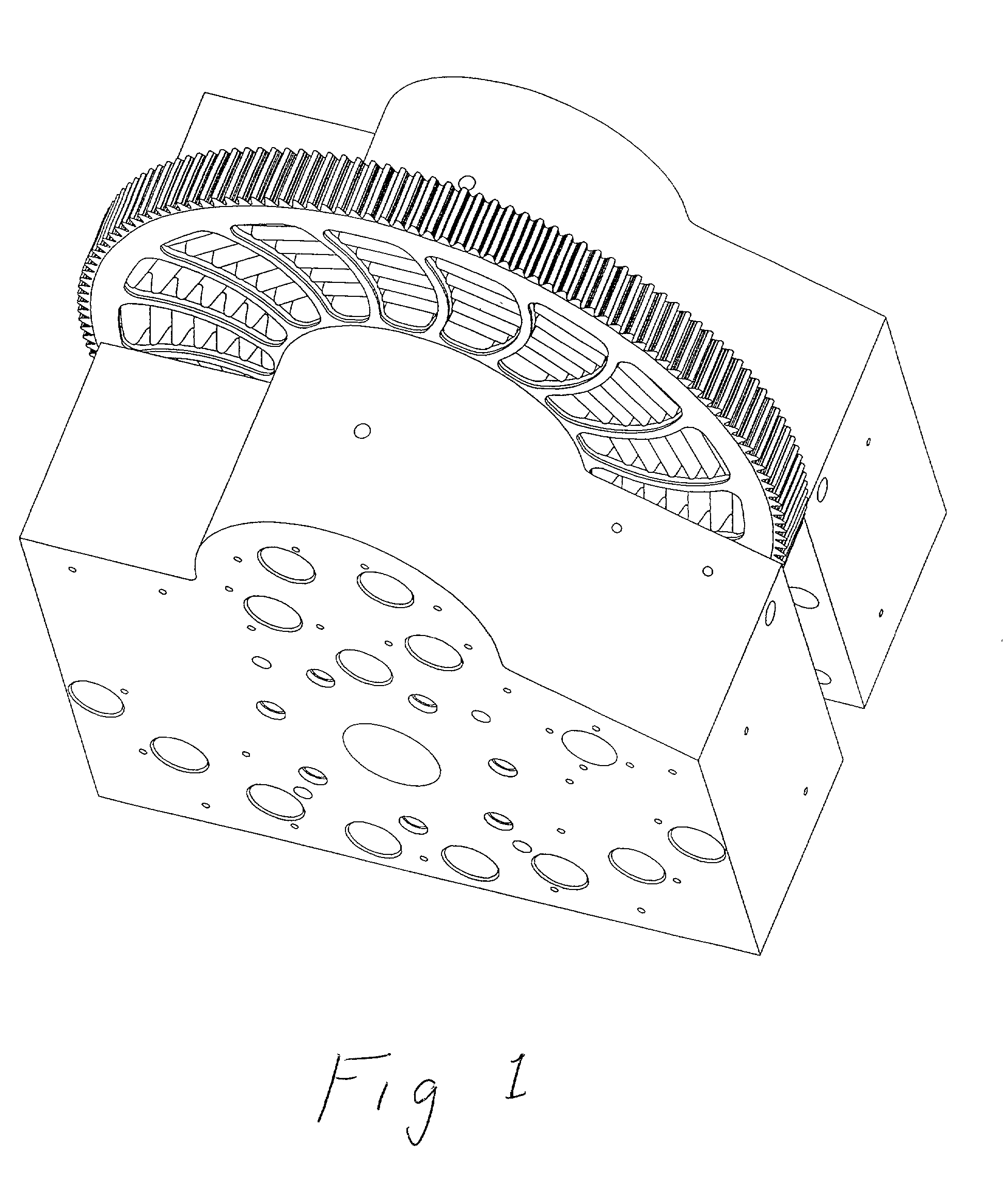
waves by milling the grooves into the rectangular plate. The optimum configuration of a rotary filter support plate is a shape that conforms to the inflow edge of the flow channel which defines a series of roughly
kidney shaped filter chambers separated by a web spacer portion of the disc. In such a configuration, the shape could not be machined directly into a rotary disc without considerable entry and exit areas lost to flow and without
distortion of the narrow shape of the web separating the filter chambers.
[0024] One solution to
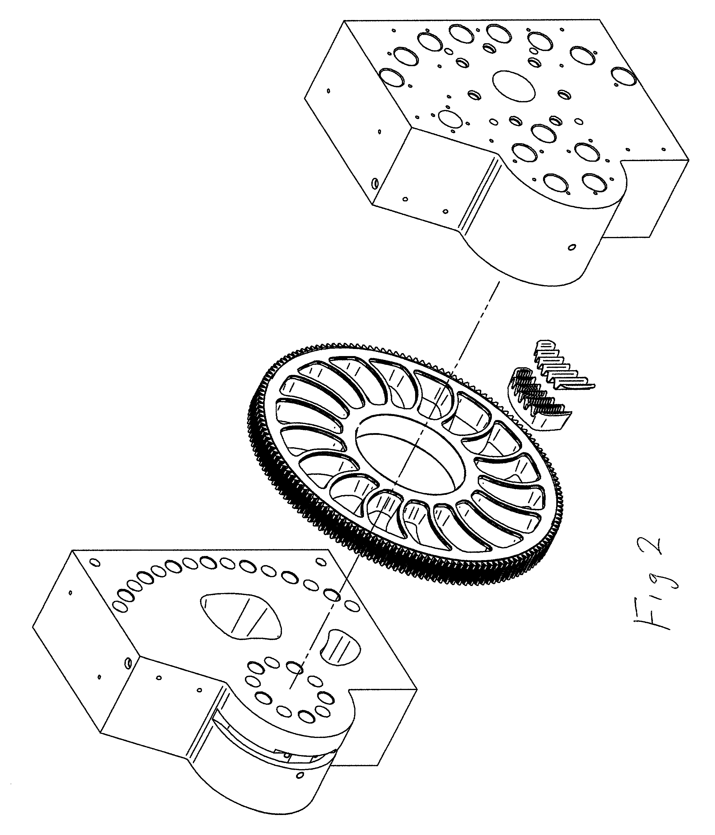
machining a filter support that allows the web to be maintained in the needed narrow strip shaped to the inflow edge of the flow chamber is to make the filter supports removable. The advent of electrodeposition machining methods allows a number of precisely shaped pockets for filter supports to be machined with angled walls holding a similarly angled filter support in place. Such a precision machined pocket and the filter support that fits into this pocket are firmly held by the matching angled sides of the parts such that the filter support does not protrude in a manner that would interfere with rotation of the disc containing the filter support from the rear of the disc. At the down flow side of the filter, away from the filter media, the angles diverge towards the filter media side so a light tap or pressure allows the removable support plate to be ejected from the filter disc. Even when the angles are the same the filter support plate is easily removable. The precision
cut filter supports are totally interchangeable so each removed support can be easily replaced with new or cleaned filter support and filter media.
[0025] This removable filter support technique and the
Electrodischarge machining methods that enable it also allow the manufacture of a wave filter. By use of removable filter and the EDM
cutting of a support plate predrilled with holes first into a series of wave shapes across the filter support plate then taking the
wave form containing filter support and
cutting the angled edges of the filter chamber shape is possible. A wave filter can be effectively manufactured.
[0026] The wave in itself is a major advance but it is one that has problems. The corrugated shape of the filter media set on top of the filter support is such that
thermal expansion differences, pressure
backup or material
backup from the downside (filtered or filtrate side) of the filter can easily cause a bow in the already corrugated filter media and allow the filter media to project away from the filter support and place the filter media in a position that allows it to be mangled between the side plate and the
rotating disc such that the sealing surface of the filter is damaged. The rehology of the polymers filtered and the spring like shape of the waved filter media as well as the common use of stiff filter medias such as
metal screens makes this a major problem. In filters made of cloth or relatively limp fibers this would not be a problem. The filter media does not cause a problem in many pleated support uses because these are used for fluid (low
viscosity & high flow) materials as opposed to the stiff hard materials used in
polymer filtration. It turns out that a
holddown mechanism proventing motion of the filter media is needed to allow a
wave shape filter to rotate under actual operation conditions of high
viscosity, low flow filtration. It is the series of
holddown methods and mechanisms that enable success with a wave type filter.
[0027] In this invention a variety of specific
holddown methods are shown but the basic concept remains a
wave shape filter support which has a method or means of preventing the upward motion of the filter media into the space of the filter chamber where the filter media may interact adversely with critical sealing surfaces or prevent rotary motion. The specific methods of preventing this motion are tabs located at various places, rod retainers and other holddown rings or projections. While specific configurations are discussed and revealed as embodiments, the words used herein should not be construed in a broader context than the text permits and all holddowns are part of a technology that permits the use of
waves or corrugations in a filter for polymers and similar viscous materials. The concept is especially valid for rotary filters since the rotary filter is essentially unique in its use of metal to metal rotating seals.
