Heat sink including a heat dissipating fin and method for fixing the heat dissipating fin
a technology of heat dissipation fin and heat sink, which is applied in the direction of cooling/ventilation/heating modification, semiconductor/solid-state device details, semiconductor devices, etc., can solve the problems of reducing the strength of the heat dissipation fin, high processing cost, and softening of the fin
- Summary
- Abstract
- Description
- Claims
- Application Information
AI Technical Summary
Benefits of technology
Problems solved by technology
Method used
Image

Examples
example 1
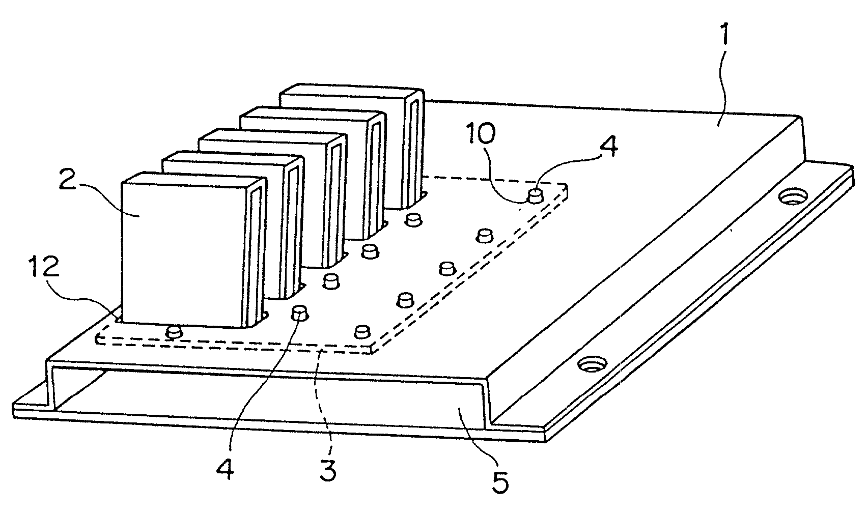
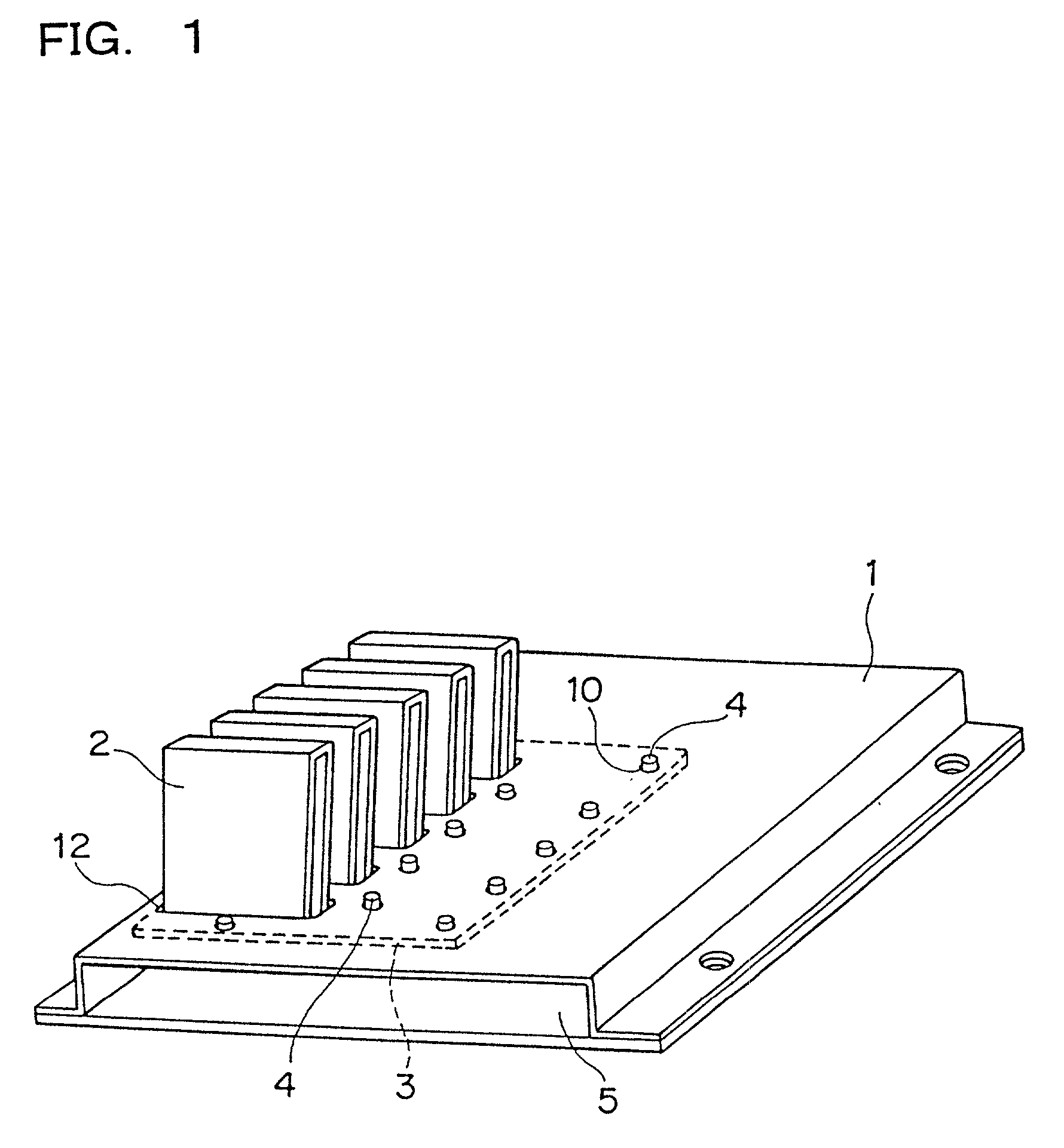
[0122] According to the present invention, a heat generating element (of 25 mm in length, 25 mm in width, 2 mm in height, and 15 W in heat generating rate) mounted on a circuit board (of 150 mm in length, 70 mm in width and 1.2 mm in thickness) of an electronic device was cooled by a heat sink including a heat dissipating fin comprising the following.
[0123] More specifically, as the base member in the heat sink, a shielding plate for electromagnetic shield (of 150 mm in length, 70 mm in width, 0.5 mm in thickness) which is made of aluminum A1050 was used.
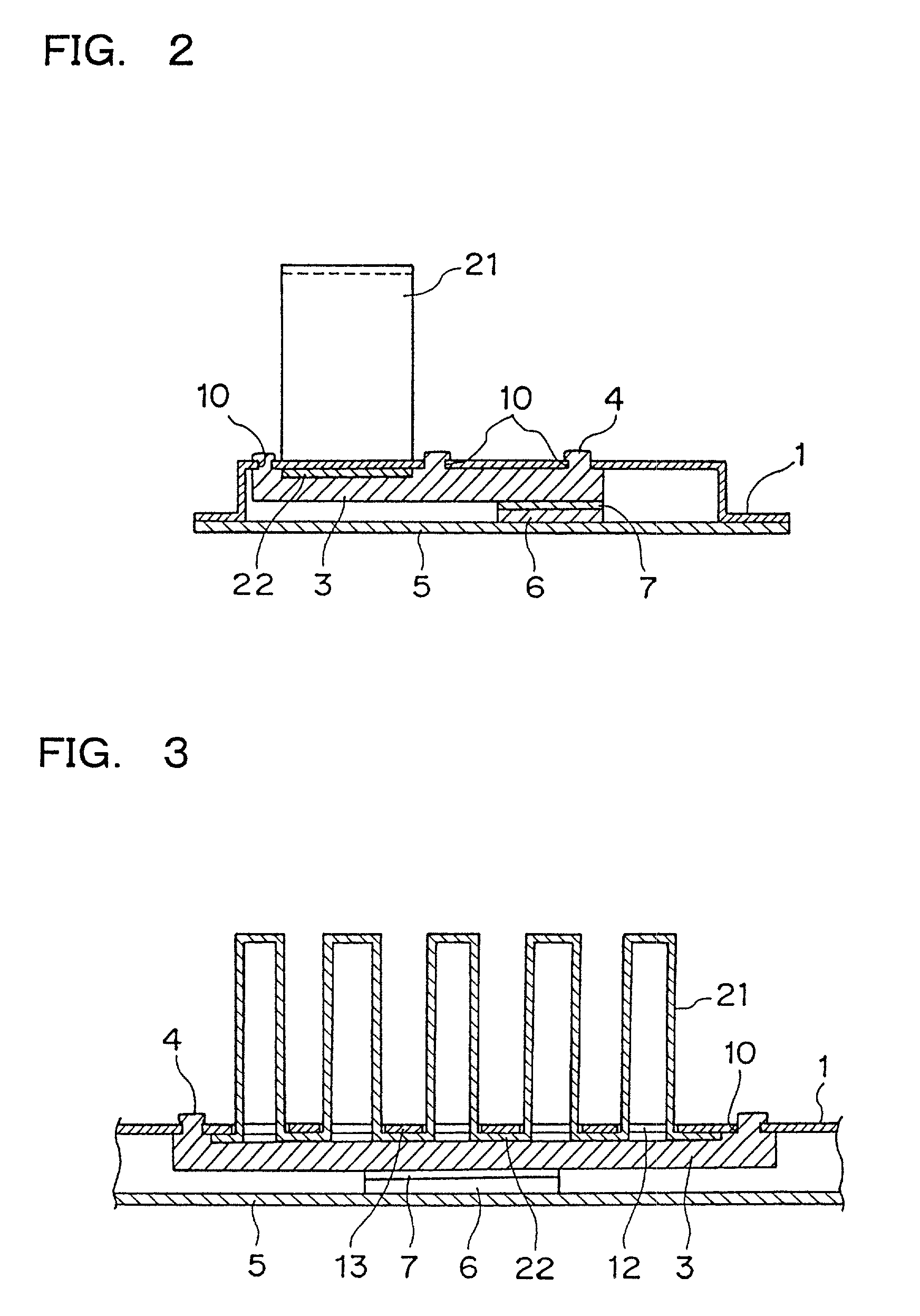
[0124] As the heat dissipating fin, a folded (corrugated) fin made of aluminum A1050 in which the height of the mountain-shaped portions is 35 mm, the pitch of mountains is 4 mm, the depth is 20 mm, the number of mountains is 8, and the thickness of the fin plate is 0.4 mm was used.
[0125] As the fitting member, a heat receiving and heat transfer block made by an aluminum die casting process (of 90 mm in length, 45 mm in width and 4 ...
example 2
[0133] A heat sink including a heat dissipating fin was prepared by embedding a heat pipe of 3 mm in diameter and 90 mm in length in the fitting member used in the Example 1.
[0134] More specifically, an L-shaped groove of 2.9 mm in width, 2.9 in depth and 90 mm in length was formed in the middle portion of the fitting member, which was positioned 45 mm laterally from one end of the fitting member. The L-shaped groove was formed therein along the longitudinal direction of the heat dissipating fin.
[0135] The other components and a method for fabricating them were the same as those shown in Example 1.
[0136] A wind inside the apparatus was also the same as described in Example 1.
[0137] The heat sink including the above-mentioned heat pipe were operated to dissipate and cool the heat generated by the heat generating element, and the surface temperature of the heat generating element was measured. As a result, a temperature rise from the atmospheric temperature was 43.degree. C. and the h...
example 3
[0138] According to the present invention, a heat generating element (of 25 mm in length, 25 mm in width, 2 mm in height, and 15 W in heat generating rate) mounted on a circuit board (of 150 mm in length, 70 mm in width and 1.2 mm in thickness) of an electronic device was cooled by a heat sink including a heat dissipating fin comprising the following.
[0139] More specifically, as the base member in the heat sink, a shielding plate for electromagnetic shield (of 150 mm in length, 70 mm in width, 0.5 mm in thickness) which is made of aluminum A1050 was used.
[0140] As the heat dissipating fin, a folded (corrugated) fin made of aluminum A1050 in which the height of the mountain-shaped portions is 35 mm, the pitch of mountains is 4 mm, the depth is 20 mm, the number of mountains is 8, and the thickness of the fin plate is 0.4 mm was used.
[0141] As the fitting member, a heat receiving and heat transfer block made by an aluminum die casting process (of 90 mm in length, 45 mm in width and 4 ...
PUM
 Abstract
Description
Claims
Application Information
 - R&D
- Intellectual Property
- Life Sciences
- Materials
- Tech Scout
- Unparalleled Data Quality
- Higher Quality Content
- 60% Fewer Hallucinations
Browse by: Latest US Patents, China's latest patents, Technical Efficacy Thesaurus, Application Domain, Technology Topic, Popular Technical Reports.
© 2025 PatSnap. All rights reserved.Legal|Privacy policy|Modern Slavery Act Transparency Statement|Sitemap|About US| Contact US: help@patsnap.com