Laser plasma EUV light source apparatus and target used therefor

a laser optical system and laser beam technology, applied in photomechanical equipment, instruments, nuclear engineering, etc., can solve the problems of large amount of debris explodedly generated, difficult continuous extraction of soft x-rays, and decreased efficiency of laser beam utilizing laser beams

Inactive Publication Date: 2002-07-18
TOYOTA MACS
View PDF0 Cites 43 Cited by
  • Summary
  • Abstract
  • Description
  • Claims
  • Application Information

AI Technical Summary

Problems solved by technology

However, in such X-ray light source apparatus the exciting laser beam is irradiated intermittently with keeping few tens of minutes to avoid drawback due to a overheating, which makes continuous extraction of the soft X-ray difficult.
Also, the debris attached to the laser optical system decreases utilizing efficiency of the exciting laser beam.
In addition, if the laser plasma soft X-ray is generated repeatedly for long time by using the tape-shape target, large amount of debris is explodedly generated in a short time to attach to the X-ray optical system and the laser optical system.
For this reason, the soft X-ray can hardly be extracted continuously for a long time, which results in low workability and productivity.
In the method for shielding the debris by the polymer film of the conventional X-ray light source apparatus, the debris floating in the vacuum chamber can hardly be shielded perfectly, so that the debris may break into the output optical system which introduces the electromagneticwave generated from the target.
Also, in the method which forms the target by injecting the particle-like metal, the soft X-ray of high brightness can hardly be generated, and the injection and the laser beam for exciting can hardly be synchronized, although generation of the debris can reduce...

Method used


Image

  • Laser plasma EUV light source apparatus and target used therefor
  • Laser plasma EUV light source apparatus and target used therefor
  • Laser plasma EUV light source apparatus and target used therefor

Examples


embodiment 1

[0092] (Embodiment 1)

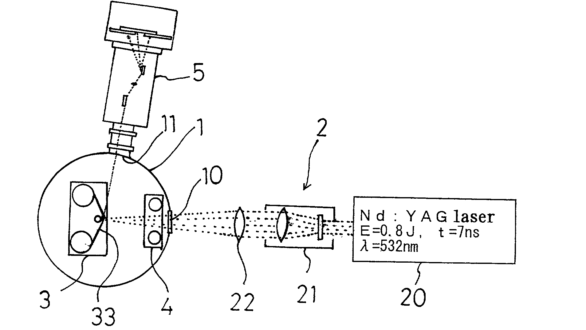
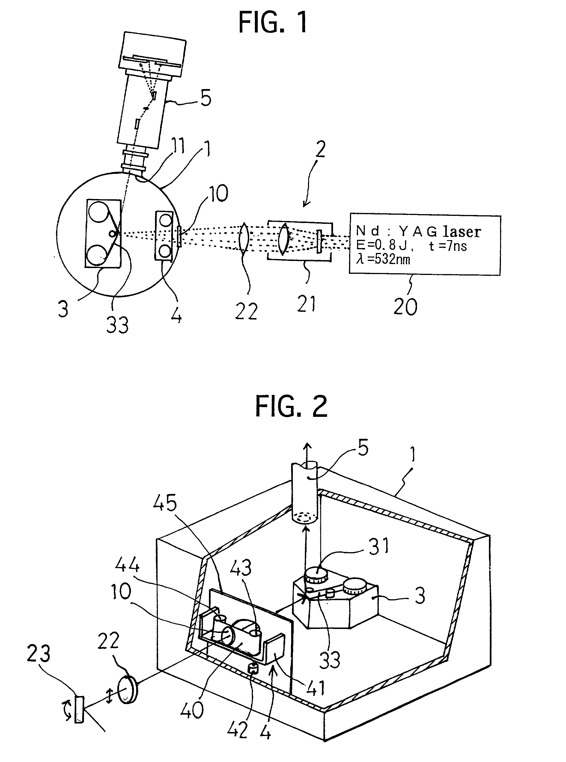
[0093] An outline of a laser plasma EUV light source apparatus of one embodiment according to the present invention is shown in FIGS. 1 and 2. This laser plasma EUV light source apparatus is mainly comprised of a vacuum chamber 1, a laser device 2 disposed outside of the vacuum chamber 1, a target drive device 3 disposed inside the vacuum chamber 1, a debris shield device 4 disposed in the vacuum chamber 1, and a plane image-forming type incidence spectroscope 5 connected to one side wall of the vacuum chamber 1.

[0094] To the vacuum chamber 1 an exhaust device (not shown) is connected to reduce pressure therein down to 10.sup.-4 Pa. On one side wall of the vacuum chamber 1 a laser incidence window 10 made of quartz glass is provided. On one side wall of the vacuum chamber 1 a connect port 11 for connecting the plane image-forming type incidence spectroscope 5 is formed.

[0095] The laser device 2 is comprised of a main body 20 emitting YAG laser beam (E=0.8 J, t=7...

experiment sample

[0106] (Experiment Sample)

[0107] By the above mentioned laser plasma EUV light source apparatus, spectrums of the electromagneticwaves generated are measured by changing construction of the target variously. In measuring, a filter to select wavelength is used to cut wavelength not more than 12.4 nm.

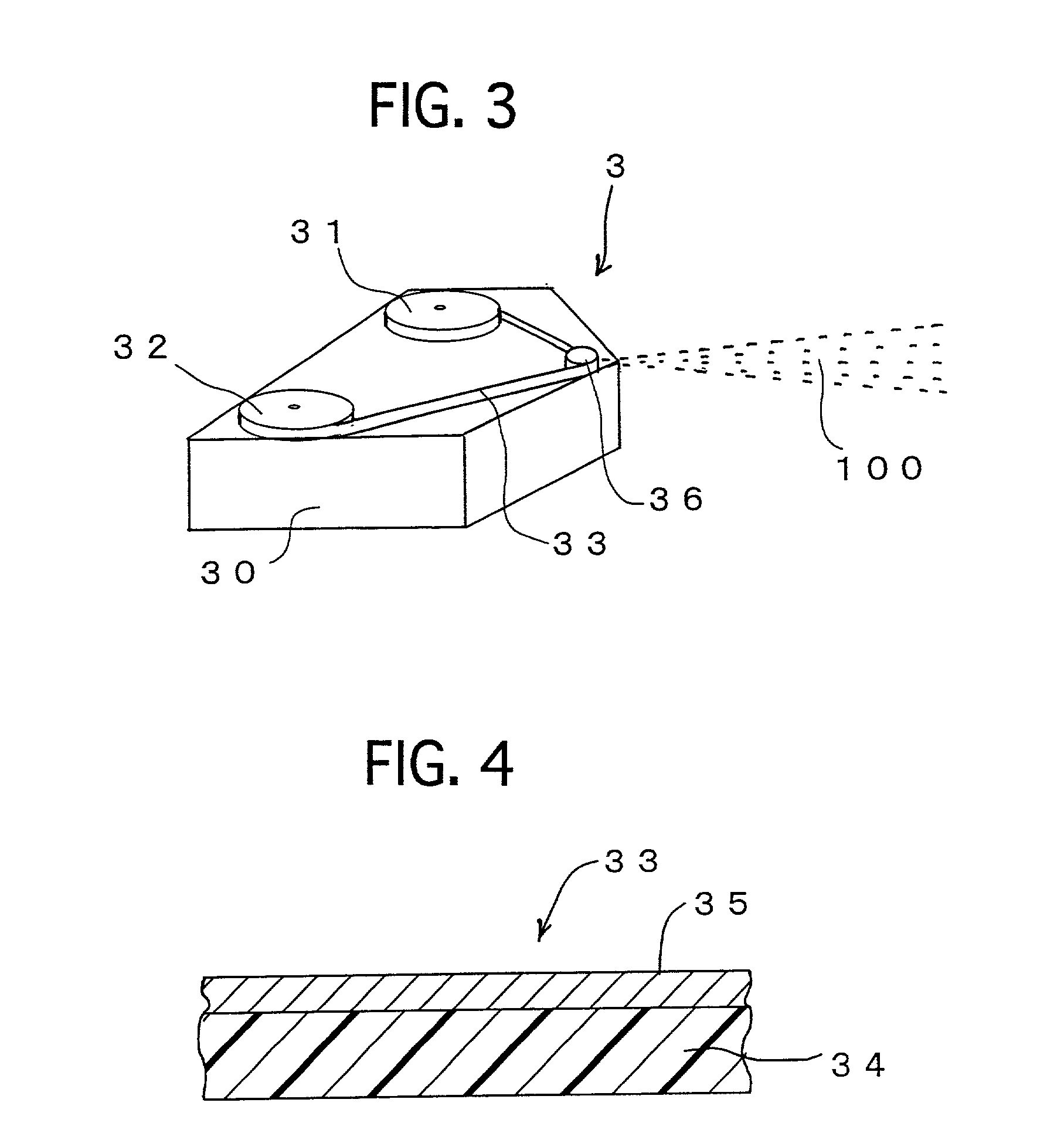
[0108] The spectrum of the target 33 in which thickness of the film layer 34 is 50 .mu.m and metal layer 35 is made of aluminium is shown in FIG. 6. The spectrum of the target in which Sn is used as the metal layer 35 is shown in FIG. 7, and the spectrum of the target in which Cu is used as the metal layer 35 is shown in FIG. 8. In any cases thickness of the metal layer 35 is 10 .mu.m.

[0109] AS apparent from these, the spectrum of Al is a line spectrum while spectrums of Sn and Cu are continuous spectrums. The continuous spectrum is convenient for the wavelength dispersion and wavelength selection, which means Sn and Cu is desirable for the target.

[0110] Next, relation between material of...

embodiment 2

[0118] (Embodiment 2)

[0119] By the way, when Cu is used as the metal layer 35, the debris deposites by about 71 .mu.m even at a position spaced by 300 mm from the focus position 36 of the target 33 provided that 1.6.times.10.sup.11 shots are made. Such amount of the deposited debris prevents reflection of the optical elements used in the plane image-forming type incidence spectroscope 5.

[0120] In view of this, in the laser plasma EUV light source apparatus of this embodiment, as shown in FIG. 10, at a root portion of the plane image-forming type incidence spectroscope 5, a pair of shutters 56 spaced are provided. Between paired shutters 56 a pair of shield plates 57 each having an opening of area 4 mm.sup.2 are disposed and between the paired shield plates 57 a shield device 6 is disposed. Another construction of the embodiment 2 is same as that of the embodiment 1. In front of the ahead shutter 56 a focus mirror 50 is disposed.

[0121] As shown in FIG. 11, the shield device 6 is comp...


PUM


Abstract

The present invention intends to generate an electromagneticwave of wavelength in an EUV area repeatedly by irradiating laser beam in high frequency more than few kHz. For such purpose, a laser plasma EUV light source apparatus is comprised of a vacuum chamber, a target disposed in the vacuum chamber, a beam irradiate means for irradiating energy beam to the target, an input optical system for introducing energy beam to the target, an output optical system being communicated with the vacuum chamber for introducing electromagneticwave generated from the target, a shield device for protecting at least one of the input optical system and output optical system from spattering particle, and a wave length select device for selecting from electromagneticwave an electromagneticwave at wavelength in the EUV area. By such construction, generation of the debris can be restricted, and generated debris is shielded by the shield device 4. In addition, the target can be supplied for long time and the laser plasma EUV light source apparatus can be made compact.

Description

[0001] 1. Field of the Invention[0002] This invention relates to a laser plasma EUV light source apparatus emitting an electromagneticwave of a EUV (Extreme Ultra Violet) area in wavelength of 10 nm to 15 nm, and a target used for the laser plasma EUV light source apparatus. The electromagneticwave of wavelength in EUV area extracted from the laser plasma EUV light source apparatus of the present invention is used for a EUV lithography, an electronic field and a chemical material field.[0003] 2. Related Background Art[0004] Recently, a X-ray light source apparatus generating a soft X-ray by irradiating laser beam to a predetermined target disposed in a vacuum chamber has been known. For example, the laser beam is focused to a surface of the target made of a plate-like or pillar-like solid metal to create a laser plasma of high density, and the soft X-ray generated from the freely expanded plasma is introduced externally through a X-ray optical system.[0005] Also, a laser beam of hig...

Claims


Application Information

Patent Timeline
IPC IPC(8): G21K5/08G03F7/20G21K5/00H01L21/027H05G2/00H05H1/24
CPCB82Y10/00G03F7/70033G03F7/70916H05G2/001
Inventor NISHIMURA, YASUHIKOAZUMA, HIROZUMI
Owner TOYOTA MACS
Why Eureka
Try Eureka