Liquid phase growth methods and liquid phase growth apparatus

a technology of liquid phase growth and growth method, which is applied in the direction of crystal growth process, chemistry apparatus and processes, polycrystalline material growth, etc., can solve the problems of wasting material of deposited film, the possibility of contact failure, and the worsening of the global environmen

Inactive Publication Date: 2002-08-15
CANON KK
View PDF0 Cites 11 Cited by
  • Summary
  • Abstract
  • Description
  • Claims
  • Application Information

AI Technical Summary

Problems solved by technology

Global environments are becoming worse because of emission of earth-warming gases such as carbon dioxide, nitrogen oxides, etc. from combustion of petroleum in thermal power generation, combustion of gasoline in automotive engines, and so on.
When the deposited film on the wafer has dispersion of thickness as described above, there is a possibility of contact failure, for example, when electrodes are attached to the surface of the deposited film in production of solar cell.
In addition, since the thickness of the deposited film has to be determined in the thin part for sufficient absorption of light, the thick part becomes over specifications and thus the material of the deposited film is wasted.
Besides, where the deposited film is thick, the peripheral part of the film is too thick for photocarriers to reach the electrodes because of the too large thickness, which degrades light conversion efficiency.
In the case of semiconductor devices other than the solar cells, the dispersion of thickness of the deposited film will require different design between in the central part and in the peripheral part of the wafer, which will increase the number of steps and, in turn, increase the production cost.

Method used


Image

  • Liquid phase growth methods and liquid phase growth apparatus
  • Liquid phase growth methods and liquid phase growth apparatus
  • Liquid phase growth methods and liquid phase growth apparatus

Examples


embodiment 1

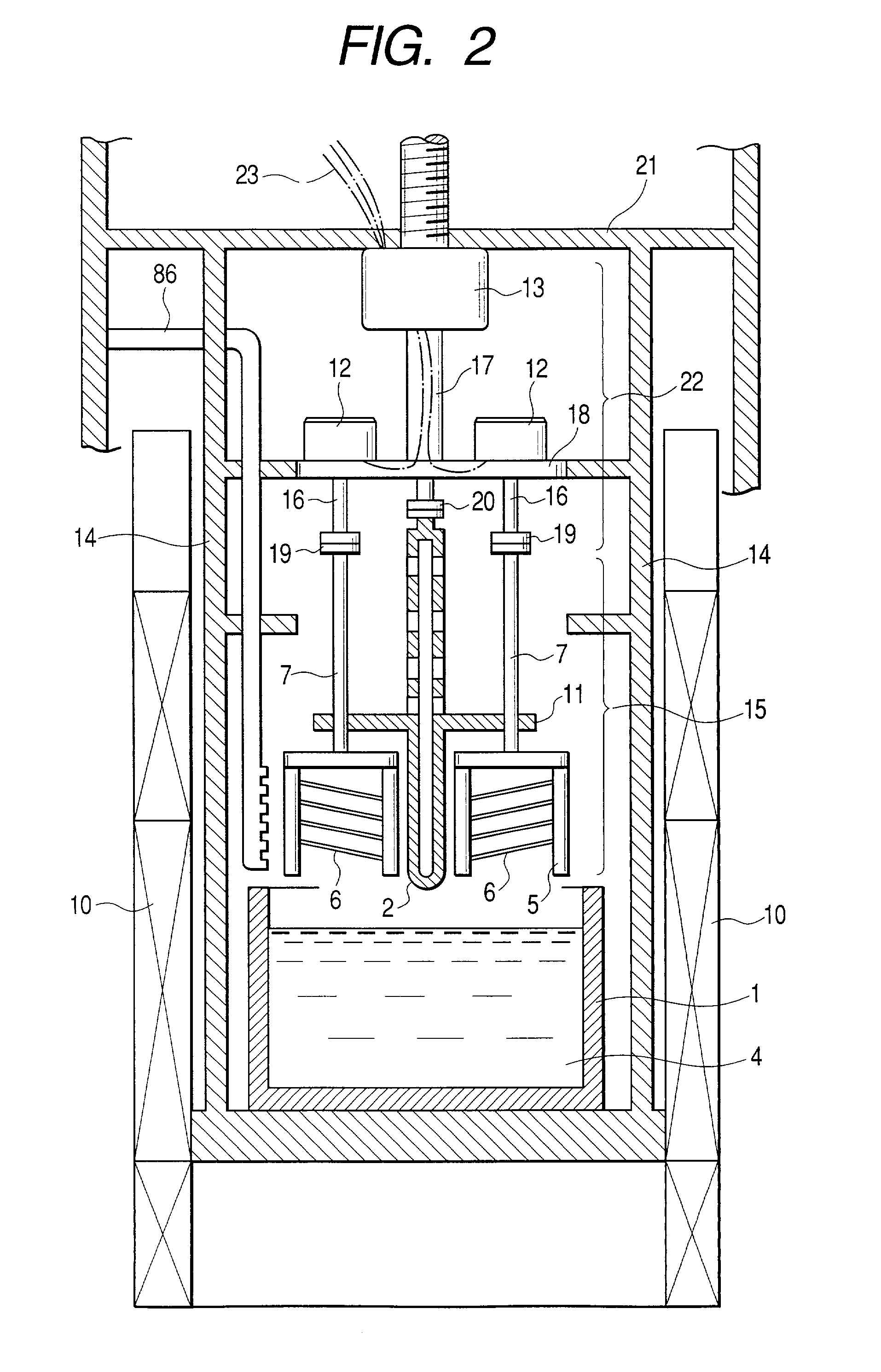
[0059] Next, as shown in FIG. 3C, a p.sup.- type Si layer 25 of an epitaxial layer (single crystal) is grown on the porous Si layer 27 by liquid phase growth. The thickness of this layer is 20 to 50 .mu.m. In the case of Embodiment 1, this epitaxial layer is the deposited film of the present invention. This step is carried out by the liquid phase growth apparatus and method of the present invention described referring to FIGS. 1A and 1B and FIG. 2. The details will be described below.

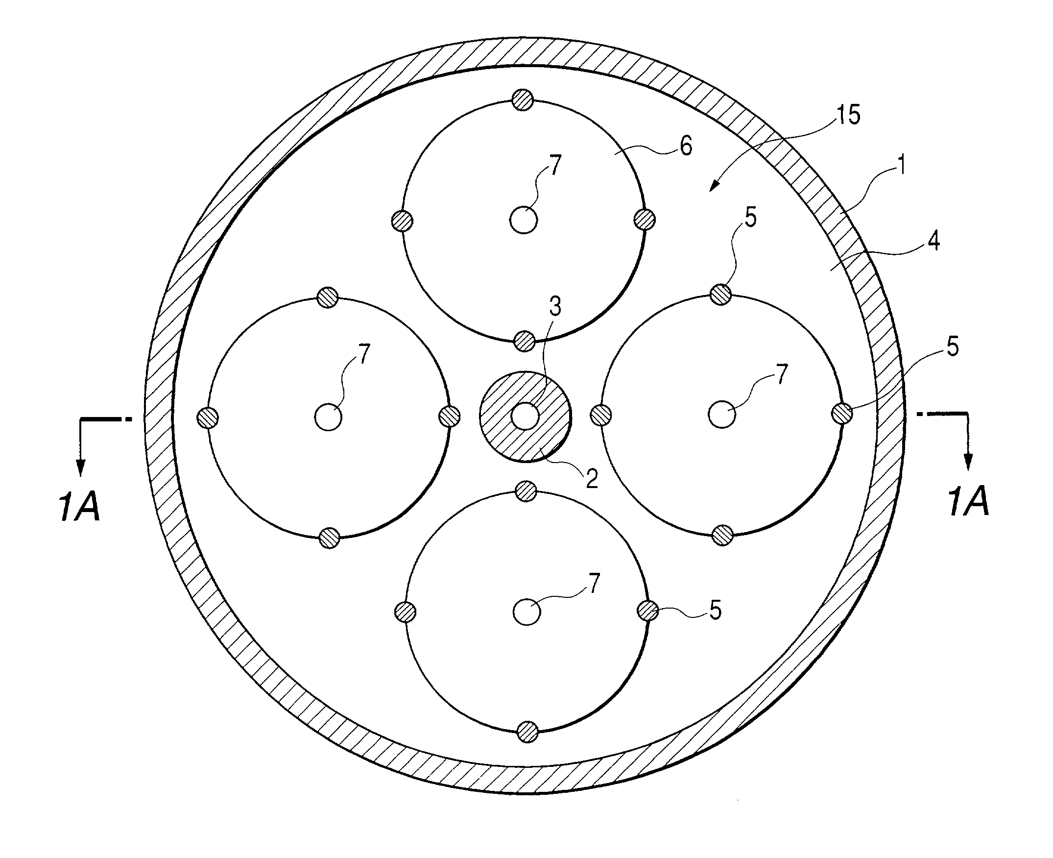
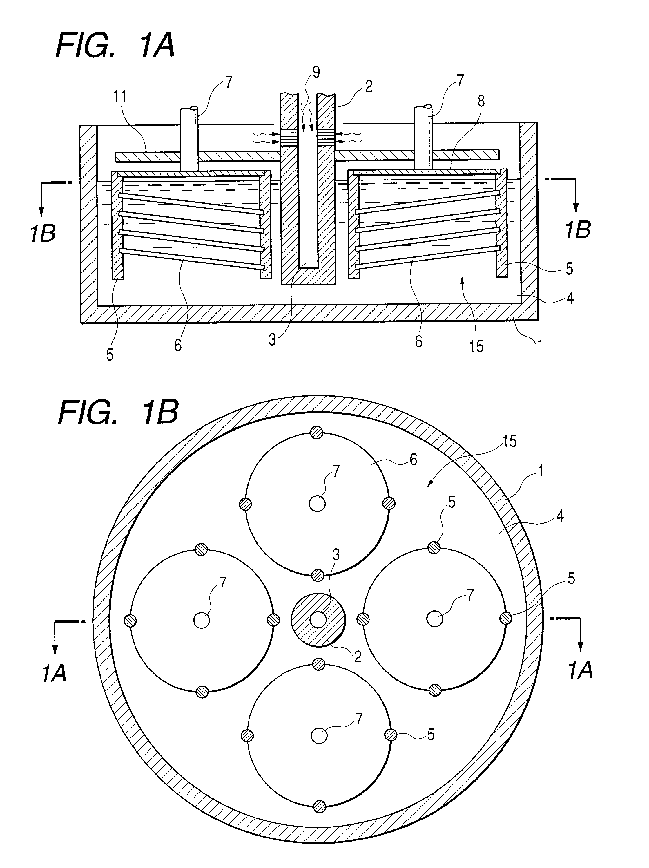
[0060] First, to-be-dissolved Si wafers as washed with dilute hydrofluoric acid or the like are set on the wafer cassette 15. The wafer support pins 5 are provided with slots for Si wafers to be inserted thereinto. The Si wafers are slid into the slots to be supported thereon. The slots of the wafer support pins 5 are formed so as to support the Si wafers obliquely, in order to prevent the solution 4 from remaining on the Si wafers when the Si wafers 6 are lifted up from the solution 4.

[0061] Next, the ...

embodiment 2

[0068] In Embodiment 2, the central part of the crucible is of hollow structure. The atmospheric gas is made to flow through this hollow structure (vent hole), which enhances the cooling effect of the central part of the solution. In Embodiment 2, four wafer cassettes 15 are immersed into one crucible. FIGS. 7A and 7B are a longitudinal cross-sectional view and a horizontal cross-sectional view, respectively, of the wafer cassettes and the crucible in Embodiment 2. The reference numerals of the components are the same as those in the foregoing figures. FIG. 8 is a cross-sectional view of the apparatus in a state in which the wafer cassettes are lifted from the crucible 1. Numeral 86 designates a gas introducing tube, and 87 a gas exhaust tube. In this liquid phase growth apparatus, each wafer cassette is rotated only about its own axis by the rotation-shaft motor 12, and the revolution mechanism as in Embodiment 1 is not provided, which simplifies the structure. As shown in FIGS. 7A...

embodiment 3

[0069] In Embodiment 3, the central part of the crucible storing the solution is also of hollow structure, as in Embodiment 2. The atmospheric gas is also made to flow through the hollow structure (vent hole), which enhances the cooling effect of the central part of the solution. However, there is only one wafer cassette provided, and each Si wafer has a hole in the central part. FIGS. 9A and 9B are a longitudinal cross-sectional view and a horizontal cross-sectional view, respectively, of the wafer cassette and crucible in Embodiment 3. Reference numerals of the components are the same as those in the foregoing figures. The sectional view of FIG. 9A is a cross section taken along a line 9A-9A in the sectional view of FIG. 9B. The sectional view of FIG. 9B is a cross section taken along a line 9B-9B in the sectional view of FIG. 9A. In Embodiment 3 each Si wafer 6 is hexagonal and a hexagonal hole is bored in the central part thereof. While the Si wafers 6 are immersed into the cruc...


PUM

PropertyMeasurementUnit
sizeaaaaaaaaaa
temperaturesaaaaaaaaaa
temperatureaaaaaaaaaa

Abstract

Provided are a liquid phase growth method including a step of immersing a substrate in a crucible storing a solvent having a growth material dissolved therein; and a step of cooling the solvent from an interior thereof, and a liquid phase growth apparatus for use in the method, by which a temperature difference of a solution is decreased and by which a deposited film is formed in a uniform thickness.

Description

[0001] 1. Field of the Invention[0002] The present invention relates to liquid phase growth methods and liquid phase growth apparatus and, more particularly, is suitably applicable to liquid phase growth methods and liquid phase growth apparatus of an immersion type in which a substrate of wafer size is held by a jig and immersed into a solution containing a growth material.[0003] 2. Related Background Art[0004] Global environments are becoming worse because of emission of earth-warming gases such as carbon dioxide, nitrogen oxides, etc. from combustion of petroleum in thermal power generation, combustion of gasoline in automotive engines, and so on. In addition, there is future concern about a drain of crude oil and attention is thus being drawn toward power generation with solar cells as clean energy sources.[0005] Since thin-film crystal silicon (Si) solar cells have a thin power-generating layer and are made using a small amount of the source material of Si, there is a perspecti...

Claims


Application Information

Patent Timeline
Patent Type & Authority Applications(United States)
IPC IPC(8): C30B19/02C30B19/04C30B19/06C30B19/08C30B29/06C30B29/08C30B29/42H01L21/208
CPCC30B19/02C30B19/04C30B19/06C30B19/08
Inventor IWANE, MASAAKINAKAGAWA, KATSUMISAITO, TETSUROSHOJI, TATSUMIYOSHINO, TAKEHITONISHIDA, SHOJIUKIYO, NORITAKAMIZUTANI, MASAKI
Owner CANON KK
Why Eureka
Try Eureka