Color laser display apparatus having fluorescent screen scanned with modulated ultraviolet laser light

a color laser and fluorescent screen technology, applied in the direction of picture reproducers using projection devices, semiconductor lasers, instruments, etc., can solve the problems of low energy conversion efficiency of gas laser lasers, large size and cost of gas laser light sources, and noise, longitudinal mode competition, etc., to achieve the effect of increasing output power

Inactive Publication Date: 2002-09-05
FUJIFILM CORP +1
View PDF11 Cites 94 Cited by
  • Summary
  • Abstract
  • Description
  • Claims
  • Application Information

AI Technical Summary

Problems solved by technology

However, the laser light sources using gas lasers have low energy conversion efficiency, which is typically 0.1%, and require a water cooling system.
In addition, the size and cost of the laser light sources using the gas lasers are great.
In addition, in the laser-diode-excited SHG solid-state lasers, a kind of noise, called longitudinal mode competition, occurs when the output power is increased.
However, if single-mode oscillation is r

Method used


Image

  • Color laser display apparatus having fluorescent screen scanned with modulated ultraviolet laser light
  • Color laser display apparatus having fluorescent screen scanned with modulated ultraviolet laser light
  • Color laser display apparatus having fluorescent screen scanned with modulated ultraviolet laser light

Examples


first embodiment

[0040] First Embodiment

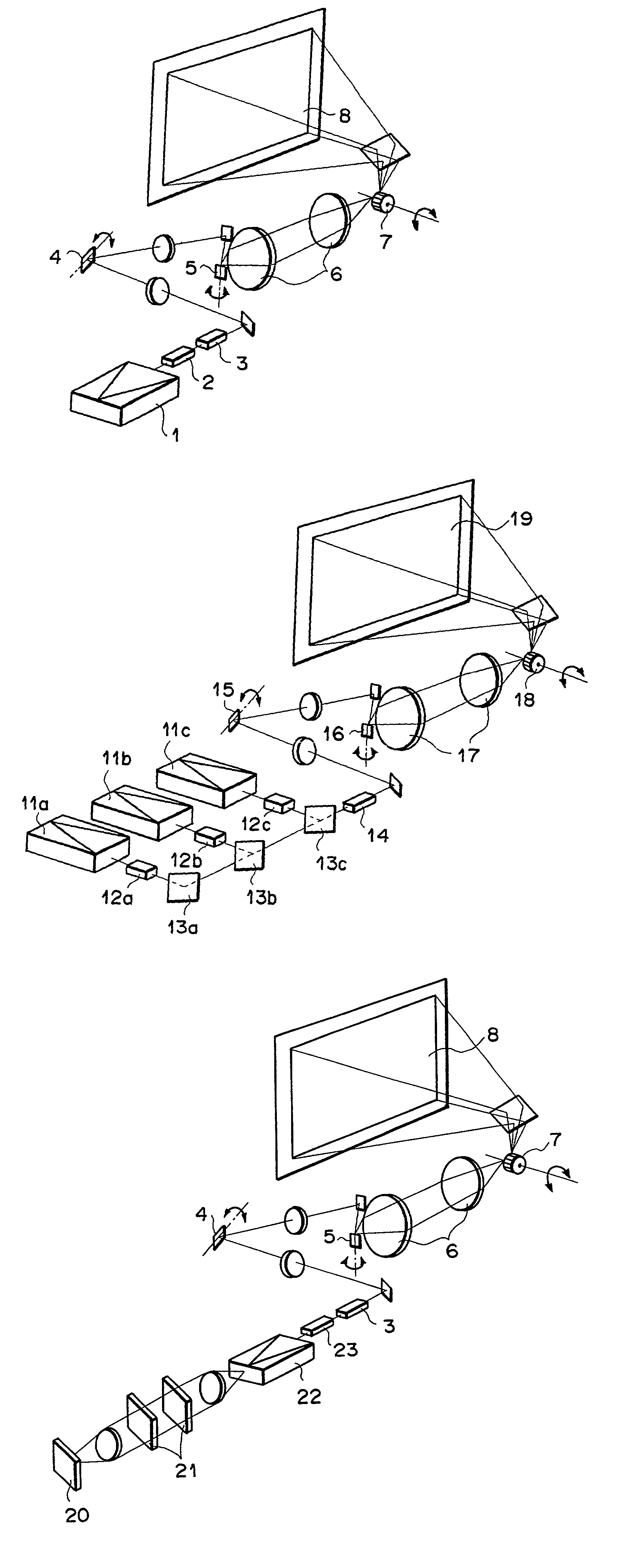
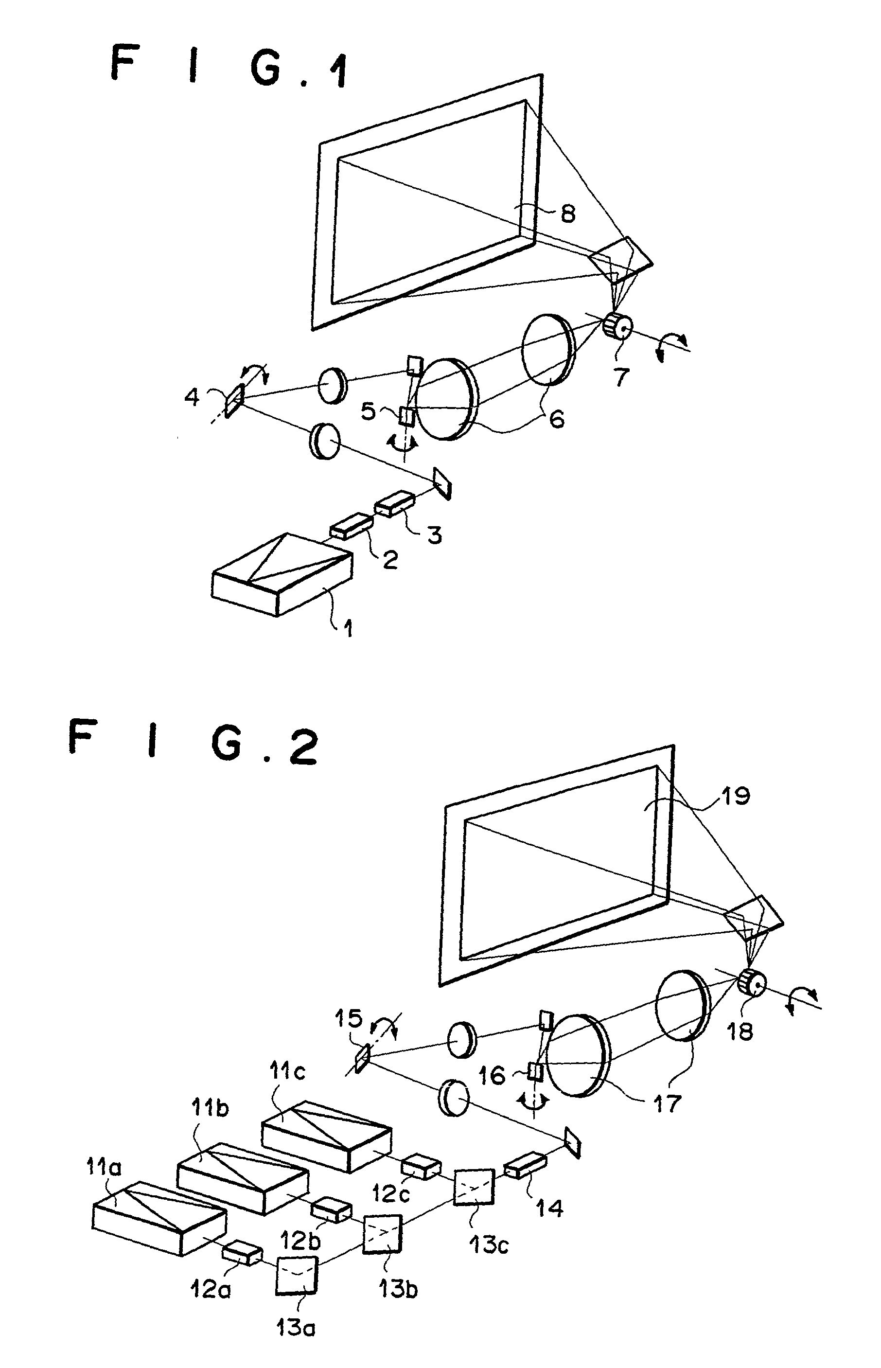
[0041] FIG. 1 is a diagram illustrating the construction of the color laser display apparatus as the first embodiment of the present invention. In the construction of FIG. 1, 1 denotes a semiconductor laser device, 2 denotes a modulator, 3 denotes an electrooptic deflector, 4 denotes a wobbling galvanometer, 5 denotes a galvanometer for vertical deflection (sub-scanning), 6 denotes relay lenses, 7 denotes a polygon mirror, and 8 denotes a screen.

[0042] The semiconductor laser device 1 is a GaN semiconductor laser device of a tapered-amplifier type having an output of three watts. The semiconductor laser device 1 functions as the aforementioned laser light source, and emits ultraviolet laser light. The intensity of the ultraviolet laser light is modulated by the modulator 2. The electrooptic deflector 3 is provided for correcting irregularity in the raster scan pitch. The galvanometers 4 and 5 are provided for deflecting the ultraviolet laser light in the verti...

second embodiment

[0045] Second Embodiment

[0046] FIG. 2 is a diagram illustrating the construction of the color laser display apparatus as the second embodiment of the present invention. In the construction of FIG. 1, 11a, 11b, and 11c each denote a semiconductor laser device, 12a, 12b, and 12c each denote a modulator, 13a, 13b, and 13c each denote a dichroic mirror, 14 denotes an electrooptic deflector, 15 denotes a wobbling galvanometer, 16 denotes a galvanometer for vertical deflection (sub-scanning), 17 denotes relay lenses, 18 denotes a polygon mirror, and 19 denotes a screen.

[0047] The three GaN semiconductor laser devices 11a, 11b, and 11c are provided for emitting three ultraviolet laser light beams corresponding to the three primary colors (red, green, and blue), respectively. Each of the semiconductor laser devices 11a, 11b, and 11c is a semiconductor laser device of a tapered-amplifier type having an output of three watts. The three modulators 12a, 12b, and 12c are provided for modulating ...

third embodiment

[0050] Third Embodiment

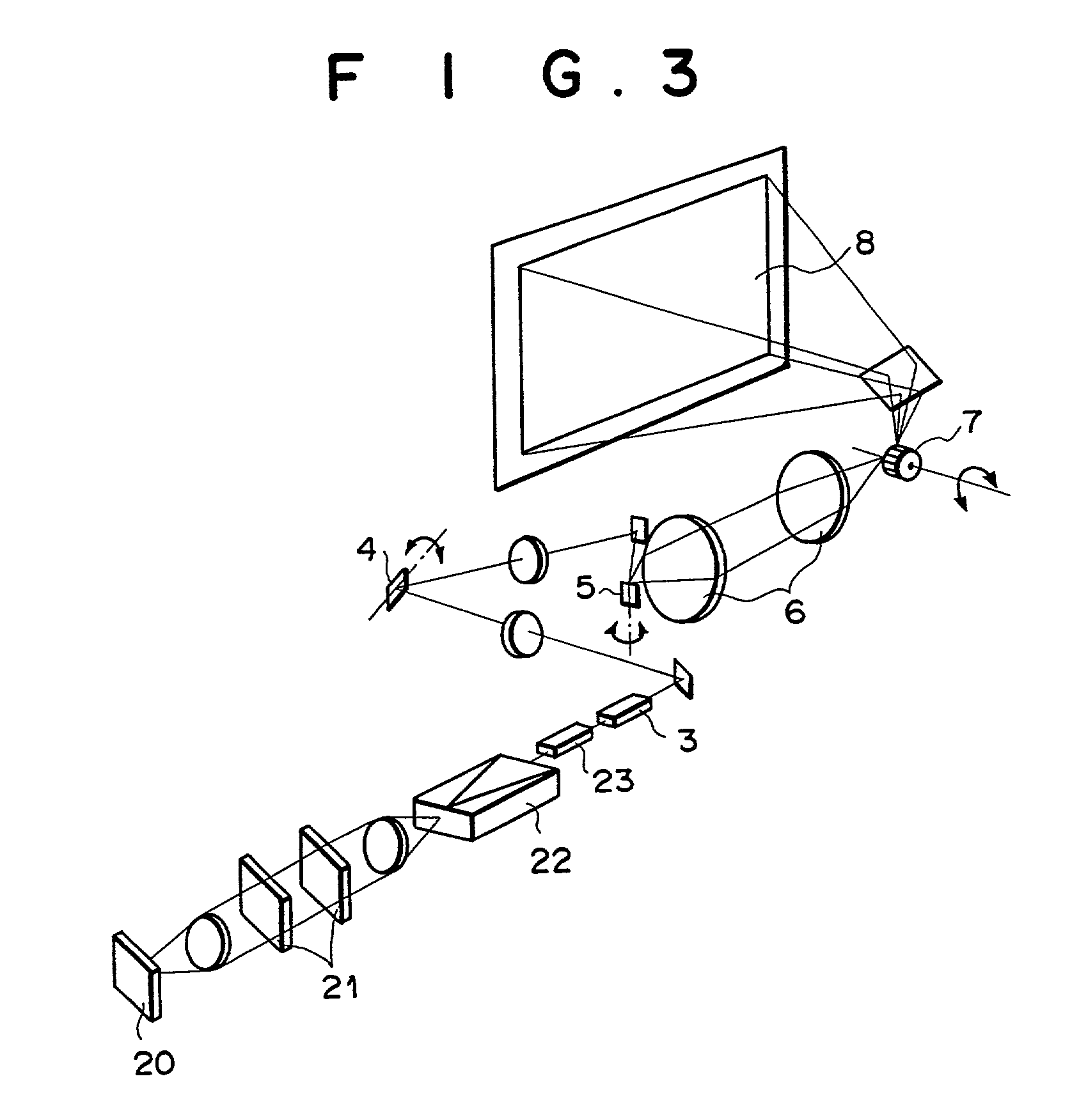
[0051] FIG. 3 is a diagram illustrating the construction of the color laser display apparatus as the third embodiment of the present invention. In the construction of FIG. 3, reference number 20 denotes a mirror, 21 denotes a Lyot filter, 22 denotes a semiconductor laser device, and 23 denotes a modulator. In FIG. 3, elements having the same reference numbers as FIG. 1 have the same function as the corresponding elements in FIG. 1.

[0052] The semiconductor laser device 22 is a semiconductor laser device of a tapered amplifier type having an output of three watts. The semiconductor laser device 22 is provided with the Lyot filter 21 and the mirror 20. A laser light beam emitted from one end of the semiconductor laser device 22 is reflected by the mirror 20, and returns to the semiconductor laser device 22 through the Lyot filter 21, which is provided for reducing the width of the oscillation wavelength distribution of the laser light beam to 0.01 .mu.m before th...


PUM


Abstract

A color laser display apparatus which contains a laser light source which emits ultraviolet laser light, a modulation unit which modulates the ultraviolet laser light, a display unit which includes a fluorescent screen, and a scanning unit which two-dimensionally scans the fluorescent screen with the ultraviolet laser light. The fluorescent screen includes, for each pixel, red fluorescent material which emits red light in response to the ultraviolet laser light, green fluorescent material which emits green light in response to the ultraviolet laser light, and blue fluorescent material which emits blue light in response to the ultraviolet laser light. The laser light source may be, for example, a semiconductor laser or a fiber laser.

Description

[0001] 1. Field of the Invention[0002] The present invention relates to a color laser display apparatus having a fluorescent screen scanned with laser light.[0003] 2. Description of the Related Art[0004] High-power laser light sources having output power in the order of watts are needed for increasing luminosity of color laser display apparatuses. Conventionally, high-power Ar.sup.+ gas lasers or Kr.sup.+ gas lasers have been used as the laser light sources in the color laser display apparatuses. However, the laser light sources using gas lasers have low energy conversion efficiency, which is typically 0.1%, and require a water cooling system. In addition, the size and cost of the laser light sources using the gas lasers are great.[0005] As reported in Laser Focus World (December 1997) p.52, recently, laser-diode-excited SHG solid-state lasers have been used as a short-wavelength visible laser light source. For example, SHG solid-state lasers which emit laser light of a green wavele...

Claims


Application Information

Patent Timeline
IPC IPC(8): H01S3/067H01S3/0941H01S5/343H04N9/31
CPCB82Y20/00H01S3/06754H01S3/0941H01S3/1613H01S3/1653H01S5/34333H04N9/3129
Inventor OKAZAKI, YOJINAGANO, KAZUHIKO
Owner FUJIFILM CORP
Why Eureka
Try Eureka