Lapping apparatus, magnetic head and method of manufacturing the same

a technology of lapping apparatus and magnetic head, which is applied in the direction of lapping machines, manufacturing head surfaces, and abrasive surface conditioning devices, etc., can solve the problems of limited element recession reduction, difficult to completely remove loose abrasives before moving, and poor lapping method

Inactive Publication Date: 2002-09-12
HITACHI GLOBAL STORAGE TECH JAPAN LTD
View PDF1 Cites 41 Cited by
  • Summary
  • Abstract
  • Description
  • Claims
  • Application Information

AI Technical Summary

Benefits of technology

0028] By lapping the workpiece by using the above-described lapping apparatus, a magnetic head can be obtained in which a lapping trace having an angle of a predetermined range with respect to the lengthwise direction of a shield portion or a magneto-resistive element is formed on the air bearing surface of magnetic head in the workpiece, and / or the formation of lapping trace crossing the shield portion or the magneto-resistive element is decreased.

Problems solved by technology

However, in the case where lapping operation is continued on the same lapping plate, it is difficult to completely remove the loose abrasives before moving on to the finish lapping.
In the above-described method, therefore, the influence of loose abrasives are exerted easily even at the stage of finish lapping operation, so that a decrease in the element recession is limited.
Also, this lapping method is nothing like satisfactory from the viewpoint of considerably decreasing the surface roughness of element surface formed by lapping and the occurrence of scratches and the like.
Therefore, even an element recession as small as several nanometers becomes a serious hindrance to the demand for decreasing the air bearing height.

Method used


Image

  • Lapping apparatus, magnetic head and method of manufacturing the same
  • Lapping apparatus, magnetic head and method of manufacturing the same
  • Lapping apparatus, magnetic head and method of manufacturing the same

Examples


Embodiment Construction

[0050] One embodiment of the present invention will now be described in detail with reference to the accompanying drawings.

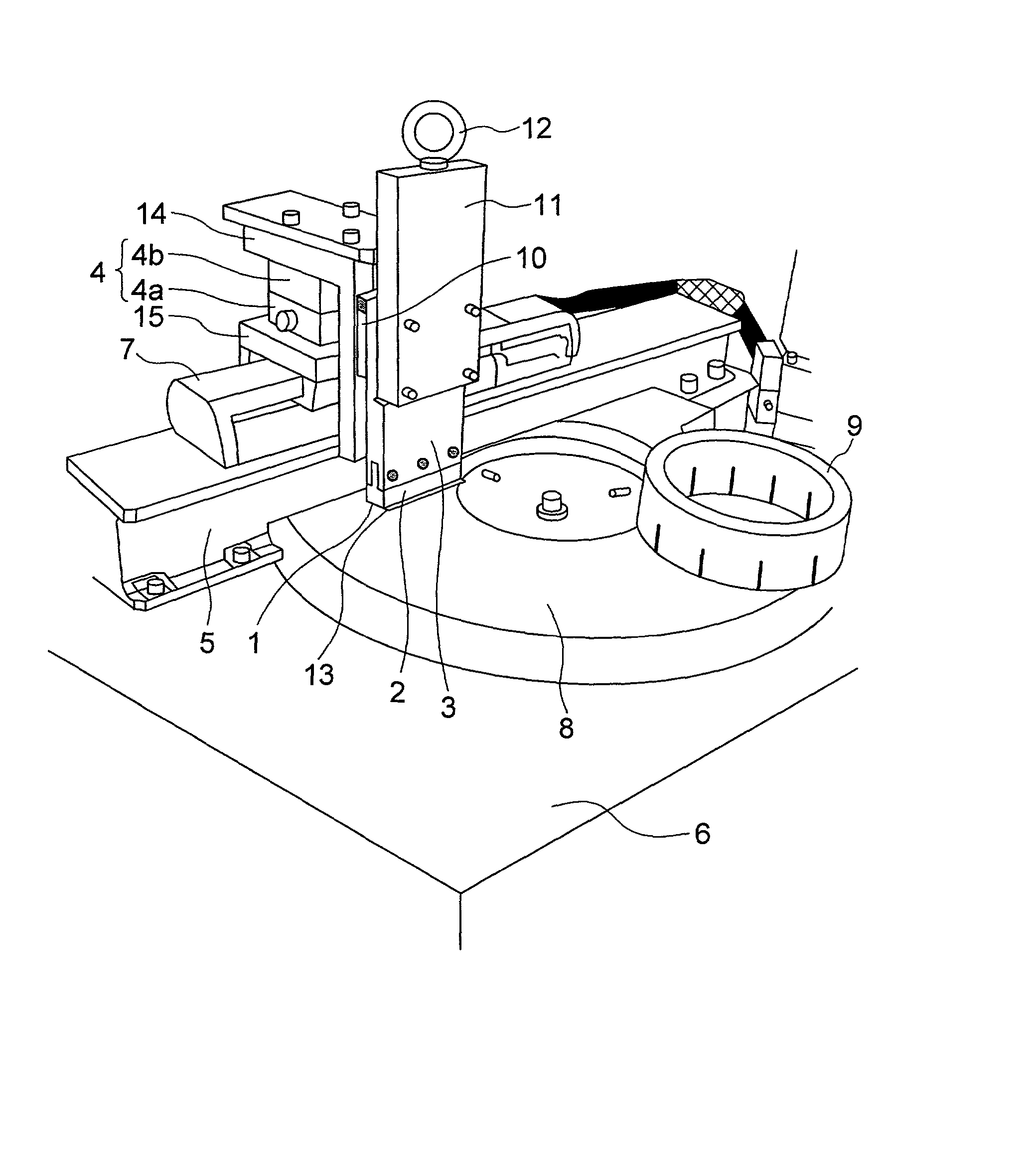
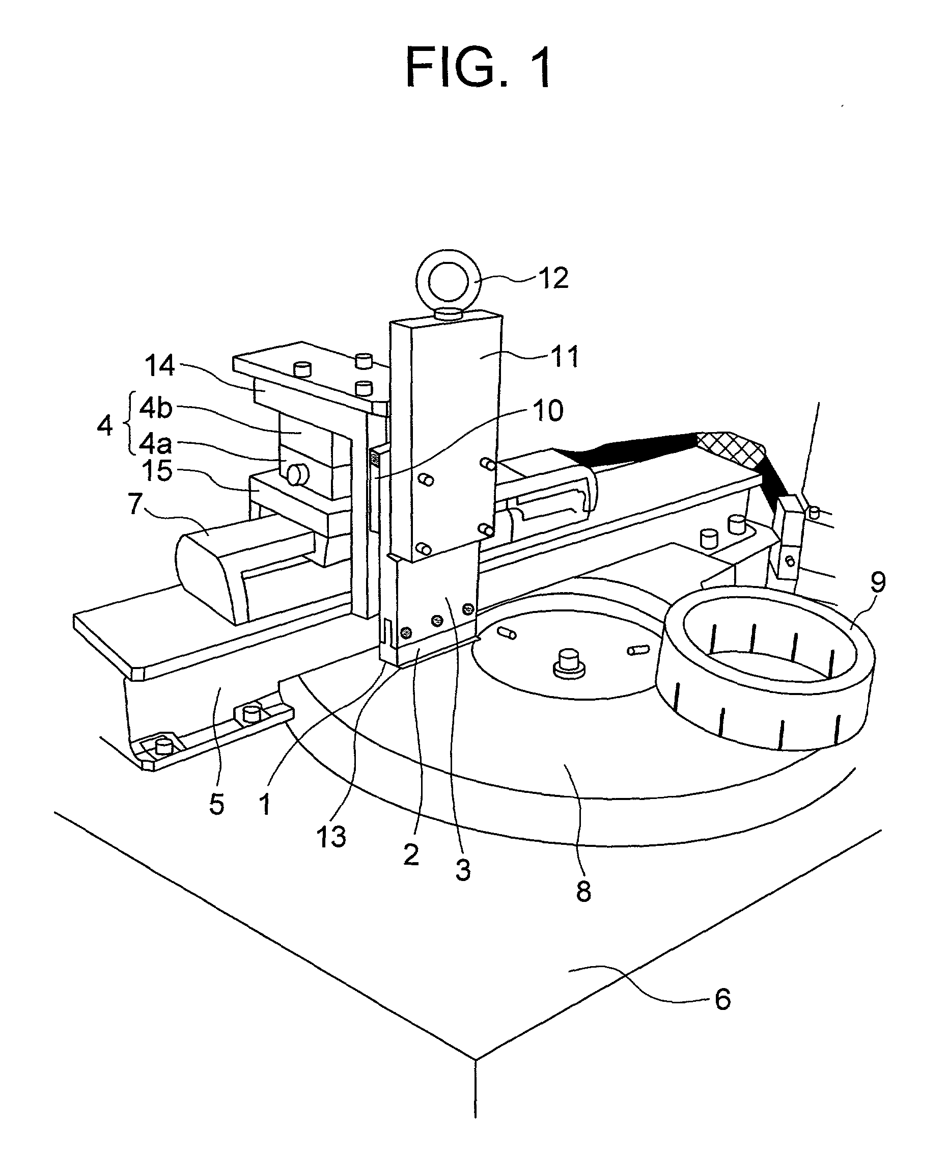
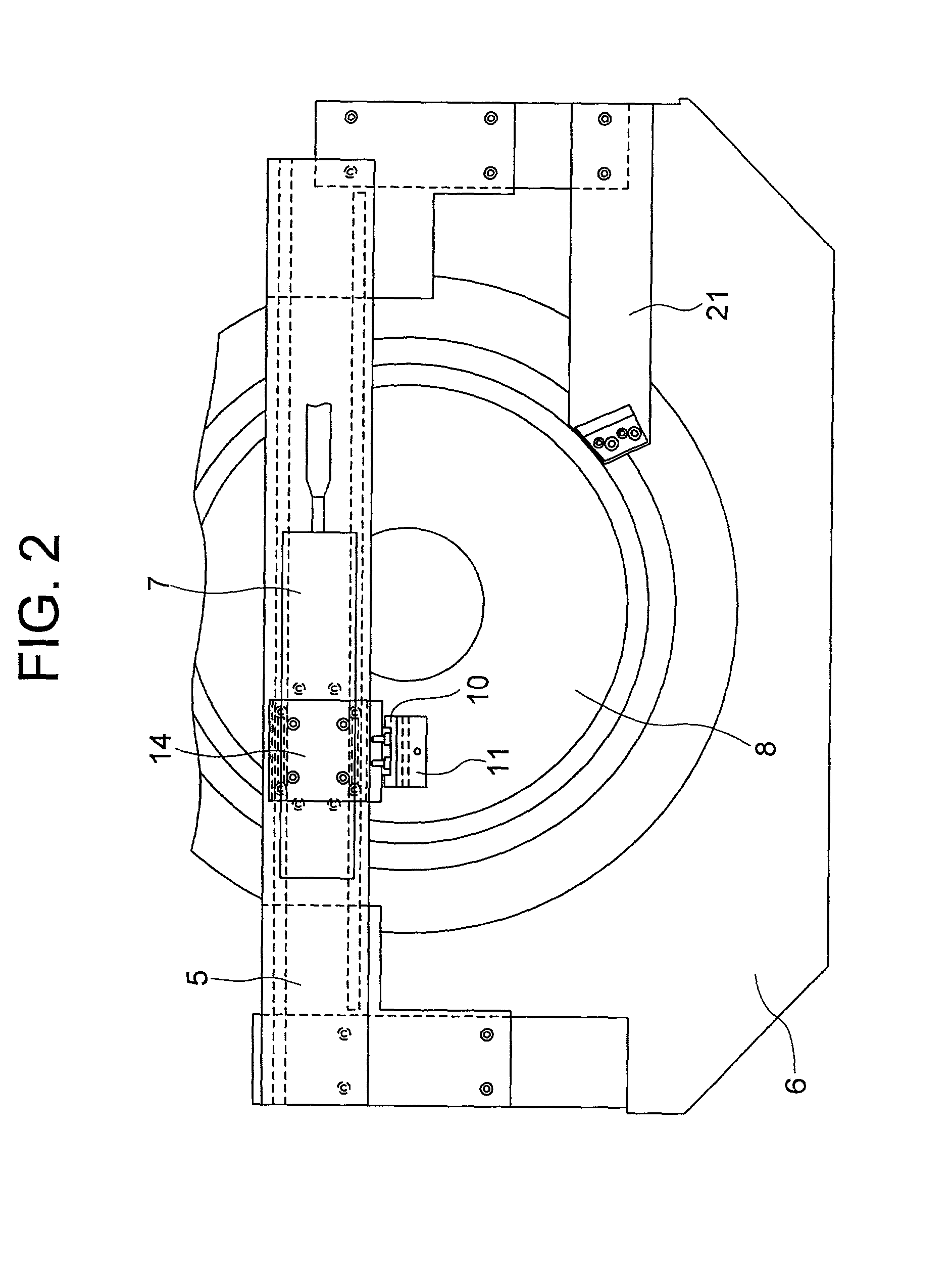
[0051] FIGS. 1 to 6 show one embodiment of a lapping apparatus in accordance with the present invention. FIG. 1 is a schematic general view of a lapping apparatus of this embodiment. In FIG. 1, a bed 6 is provided with a disk-shaped lapping plate 8, and a bridge 5 is provided over the bed 6 in a form of striding the lapping plate 8. On the bridge 5, a reciprocating motion drive unit 7 consisting of a linear actuator is installed, and an angle adjustment mechanism 4 comprising two gonio-stages 4a and 4b is mounted on a slider table 15 of the reciprocating motion drive unit 7. One end of an L-shaped slide plate 14 is attached to the angle adjustment mechanism 4, and the other end thereof is attached to workpiece holding device 3 via a linear slide guide 10. Further, the workpiece holding device 3 is mounted with a detachable workpiece holding jig 2, and the workpi...


PUM

PropertyMeasurementUnit
angleaaaaaaaaaa
heightaaaaaaaaaa
diameteraaaaaaaaaa

Abstract

An L-shaped slide plate mounted with a workpiece holding device on a slide guide is firmly attached to an angle adjustment mechanism, and a reciprocating motion drive unit mounted with the angle adjustment mechanism on a slider table is firmly attached to a bridge so that an angle between a surface of a workpiece to be lapped and a surface of a lapping plate is kept substantially constant, and also the bridge is disposed so as to stride the lapping plate. Thereby, in a state of row bar in which a plurality of magnetic head sliders run in a line, an air bearing surface of magnetic head can be lapped with high accuracy with an element recession being decreased and an occurrence of a scratch being restrained.

Description

BACKGROUND OF THE INVENTION[0001] This invention relates to a magnetic head for performing recording and reproduction of information while moving relatively with respect to a magnetic medium such as a magnetic disk, and a lapping method thereof, and a magnetic disk drive unit using the magnetic head.[0002] In recent years, in a magnetic disk drive unit, recording density has been rapidly improved. Accordingly, it has been demanded that an air bearing height of the magnetic head with respect to the magnetic recording medium should be decreased to the utmost.[0003] As shown in FIG. 7, the magnetic disk drive unit is completed by combining magnetic heads 70, each of which is fixed to a support spring 74, with magnetic disks 73, which are recording medium. Magnetically recorded information is written and read by means of the magnetic head 70 that moves over the rotating magnetic disks 73 by means of a drive unit 75.[0004] In order to create an air bearing surface of magnetic head for re...

Claims


Application Information

Patent Timeline
Patent Type & Authority Applications(United States)
IPC IPC(8): B24B19/26B24B37/04B24B37/10B24B37/30B24B41/06B24B53/007B24B53/017G11B5/187G11B5/31G11B5/39
CPCB24B37/00B24B41/06B24B53/017G11B5/3163G11B5/3903Y10T29/49046
Inventor TAKAHASHI, TOSHIOCHIBA, HIROMUSEKI, TAKATERUTANAKA, HIDEAKITAMURA, TOSHIOYAMASAKA, MINORUTAKAKURA, AKIO
Owner HITACHI GLOBAL STORAGE TECH JAPAN LTD
Why Eureka
Try Eureka