Electroluminescent device and method of producing the same

Inactive Publication Date: 2002-09-19
DENSO CORP
View PDF0 Cites 3 Cited by
  • Summary
  • Abstract
  • Description
  • Claims
  • Application Information

AI Technical Summary

Benefits of technology

0012] Accordingly, the EL device has a high insulating performance and a high water resistance. Further, in this EL d

Problems solved by technology

Further, in this EL device, the total time for forming the first and

Method used


Image

  • Electroluminescent device and method of producing the same
  • Electroluminescent device and method of producing the same
  • Electroluminescent device and method of producing the same

Examples


Example

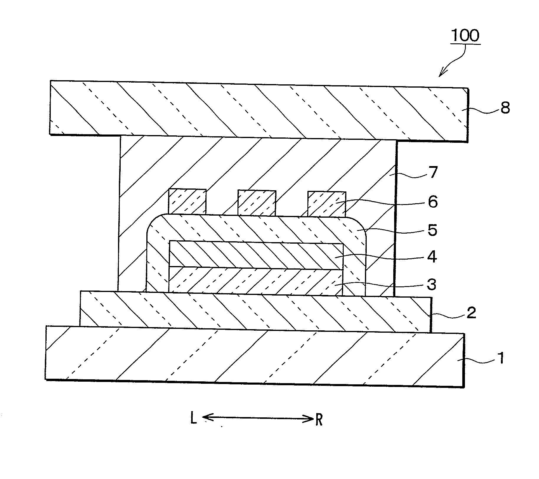
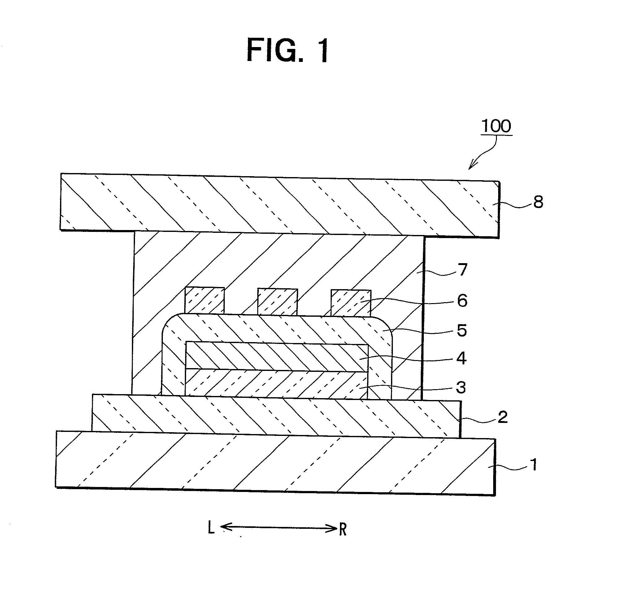
[0017] As shown in FIG. 1, an EL device 100 is constructed of an insulating substrate 1, a plurality of first electrodes 2, a first insulating layer 3, a luminescent layer 4, a second insulating layer 5 and a plurality of second electrodes 6, which are laminated on the insulating substrate 1 in this order.

[0018] The insulating substrate 1 is formed, for example, by glass substrate. The first electrodes 2 are made of a transparent and conductive material, for example, ITO (Indium Tin Oxide), ZnO (Zinc Oxide) or the like. In this embodiment, the first electrodes 2 are made of ITO. The first electrodes 2 extend in the left to right direction of FIG. 1 and are parallel.

[0019] A first insulating layer 3 is made of metal oxide. The first insulating layer 3 is not made by ALE, but is made, for example, by sputtering or vapor deposition. The first insulating layer 3 is formed on and between the first electrodes 2. Preferably, the first insulating layer 3 includes four materials, that is, ta...


PUM


Abstract

An EL device is constructed of an insulating substrate, and a first electrode, a first insulating layer, a luminescent layer, a second insulating layer and a second electrode, which are laminated on the insulating substrate in this order. The insulating layer is made by a method other than ALE, for example, sputtering or vapor deposition. The second insulating layer includes alternating layers of Al.sub.2O.sub.3 and TiO.sub.2, which are formed by ALE. The second insulating layer covers the luminescent layer and an end surface of the first insulating layer. Since the first insulating layer is not formed by ALE, the device can be manufactured with high productivity, and there is no less of performance compared to a device having two ALE insulation layers.

Description

CROSS REFERENCE TO RELATED APPLICATIONS[0001] This application is based upon and claims the benefit of Japanese Patent Application No. 2001-72448 filed on Mar. 14, 2001, the contents of which are incorporated herein by reference.BACKGROUND OF THE INVENTION[0002] 1. Field of the Invention[0003] The present invention relates to electroluminescent devices (referred to herein as EL devices) that are used for various instruments of emissive-type segment displays and matrix displays, displays of various information terminals, and the like. The present invention also relates to methods for producing the same.[0004] 2. Related Art[0005] An EL device is typically formed by laminating first electrodes, a first insulating layer, a luminescent layer, a second insulating layer, and second electrodes on an insulating glass substrate in this order. The first and the second insulating layers are made of silicon dioxide (SiO.sub.2), silicon nitride (SiN), silicon oxynitride (SiON), sitantalum pentao...

Claims


Application Information

Patent Timeline
IPC IPC(8): H05B33/10H05B33/12H05B33/22
CPCH05B33/10H05B33/12H05B33/22
Inventor INOUE, TAKASHIKATAYAMA, MASAYUKIKONDO, HIROSHI
Owner DENSO CORP
Why Eureka
Try Eureka