
Heat sink

a heat sink and heat sink technology, applied in the direction of insulated conductors, sustainable manufacturing/processing, cables, etc., can solve the problems of increasing the complexity of the board, the inability to operate the device, and the inability to meet the requirements of the devi

Inactive Publication Date: 2002-09-19
AAVID THERMALLOY LLV
View PDF24 Cites 23 Cited by
  • Summary
  • Abstract
  • Description
  • Claims
  • Application Information

AI Technical Summary

Benefits of technology

[0033] According to another aspect of the invention, a surface mounting arrangement for attaching a heat sink to a suitably prepared surface on a PCB, includes a clip formed from a resilient thermally conductive material to provide confronting surfaces and a common base therebetween, the base having a solder-compatible surface. One of the confronting surfaces is resiliently biased towards the other, but is sufficiently pliant to permit a part of a heat sink body to be inserted between the confronting surfaces, and the biased surface is formed to provide a detent adapted to cooperate with a corresponding recess in said part of a heat sink body. In this surface mounting arrangement, the clip provides a solderable element. In use the clip is oriented correctly to present the base for soldering upon the surface of the PCB to fix the clip in a generally upright position, thereby enabling a part of a suitable heat sink body to be forced home into the clip whereupon it is retained in position by inter-fitting of the detent with a recess provided for this purpose in the relevant part of the heat sink body. The resilience of the clip is sufficient to maintain the inter-fitting relationship unless the heat sink body is intentionally and forcibly removed by pulling. This aspect facilitates assembly of heat sinks upon the appropriately prepared PCB and also permits removal of the heat sink when required.

Problems solved by technology

Heat sinks are required in electronic equipment such as system boards for computers, central processing units, memory devices, control devices, power amplifiers etc., because the electronic devices typically used therein generate heat in normal usage and moreover, have an optimal operational temperature range outside of which the operational capacity of the device(s) can be impaired due to thermal degradation or overload.
This problem can only become more demanding as the processing power of products increases.
The more complex boards have to handle a considerable heat load and often the boards themselves include thermal conductors to take heat away from the devices and connecting circuitry.
While aluminum is a good material for use in heat sinks, e.g. it is lighter and cheaper than copper or copper alloys, it is not readily soldered due to its oxide layer.
While these surface mounted heat sinks are currently commercially successful, the cost thereof, and poorer thermal dissipation performance when judged against a comparable size of heat sink constructed of blackened aluminum or an aluminum alloy leads to a desire to find an alternative heat sink.
These properties of aluminum are widely recognized but aluminum has the drawback of being non-receptive to soldering.

Method used


Image

  • Heat sink
  • Heat sink
  • Heat sink

Examples


Embodiment Construction

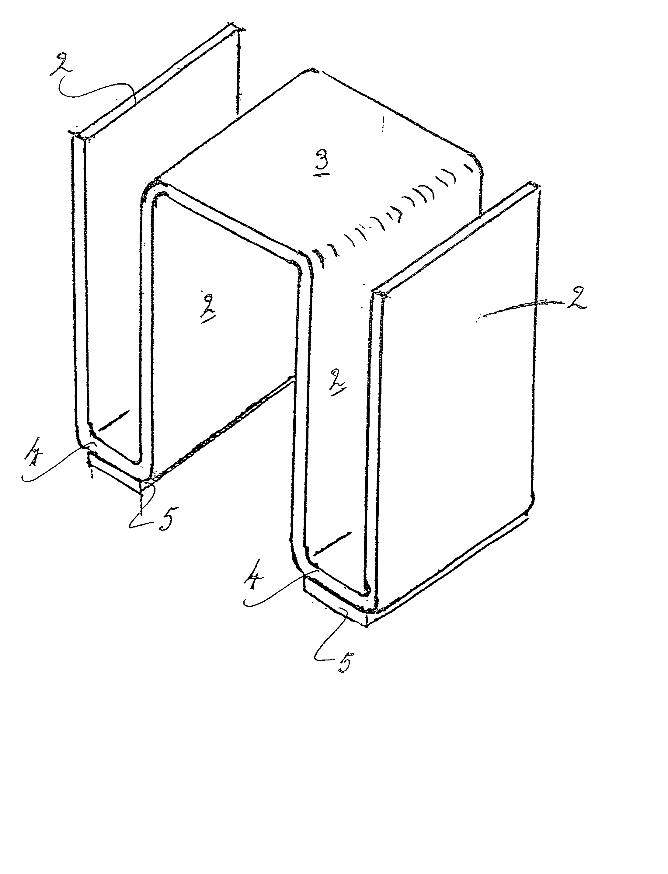
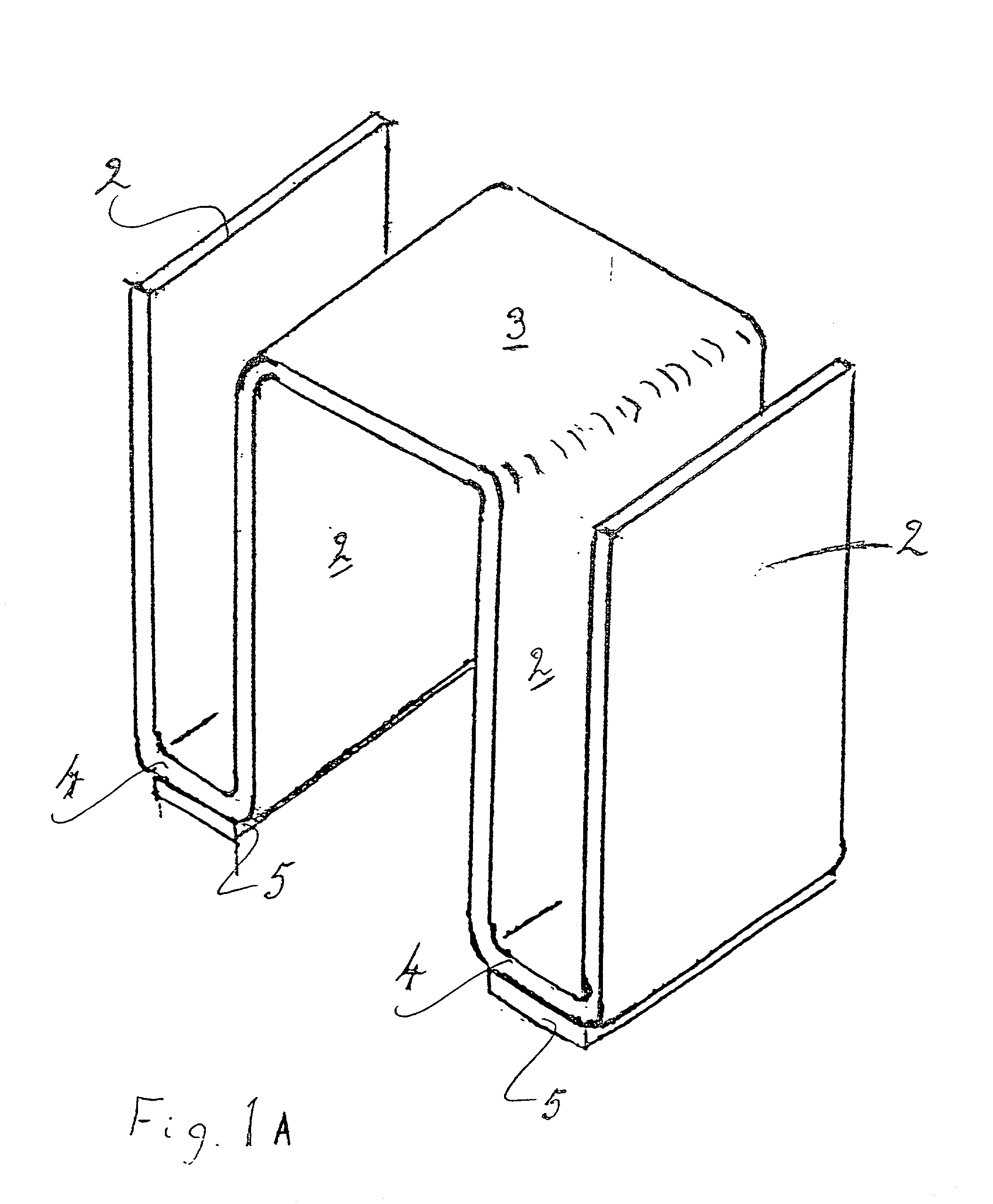
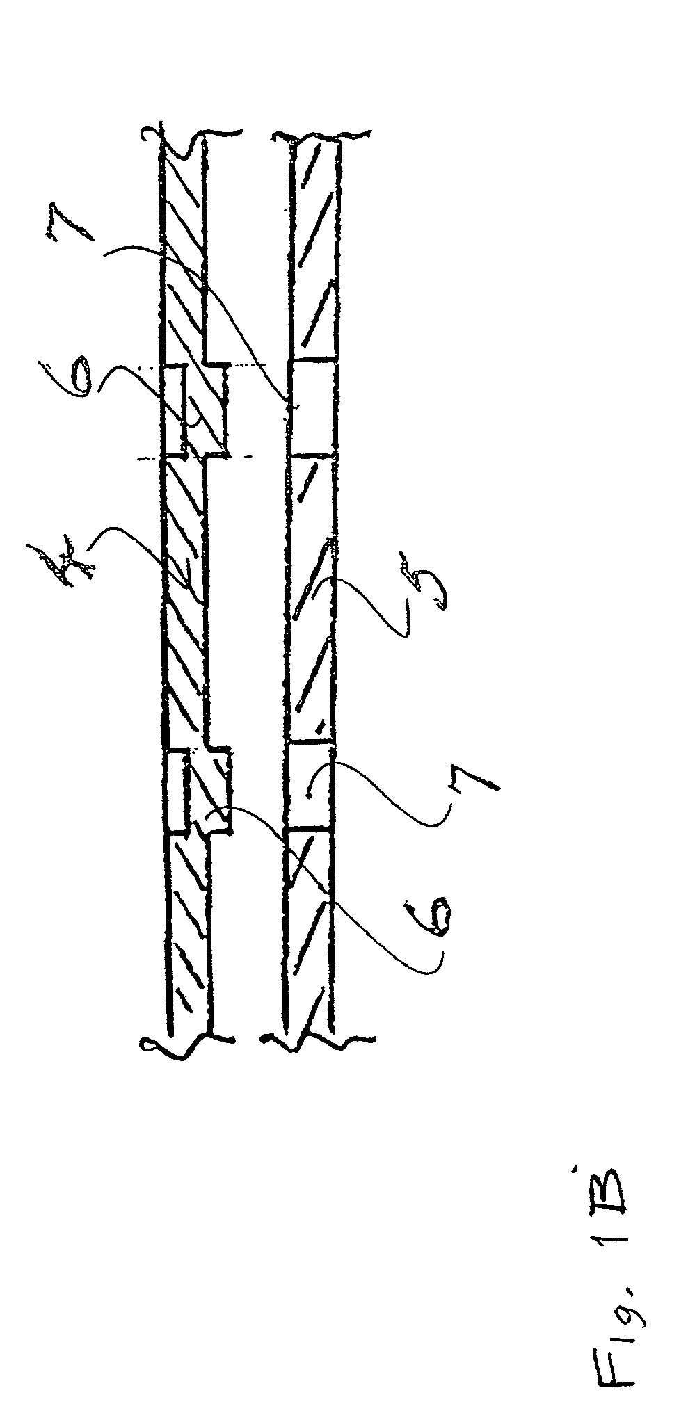
[0044] A surface mounted heat sink assembly according to one aspect of the present invention is illustrated in FIG. 1. An anodized blackened, aluminum sheet is formed to provide a finned heat sink 1 having freely extending heat dissipating fins 2 arranged on either side of a planar section 3 intended to be arranged in use over an electronic device (not shown) to be protected against heat overload. The heat sink 1 has surface mounting lands 4 at the base of the heat sink which are adapted for soldering to a substrate by a soldering technique known per se in the field, e.g. solder reflow methods, by the provision of thermally conductive solderable elements 5. These solderable elements 5 are contiguous with and extend over the surface of the lands 4, and are retained in position by a mechanical fixing (FIG. 1(b)). Such a mechanical fixing is achievable by partially shearing or semi-perforating the land to drive out a projection to provide a spigot 6 (FIG. 1b) that is inserted into a co...


PUM

PropertyMeasurementUnit
thermally conductiveaaaaaaaaaa
heataaaaaaaaaa
temperatureaaaaaaaaaa

Abstract

A composite heat sink devise includes a heat sink body formed of aluminum, the body having a pair of coplanar surfaces, and a thermally conductive solderable element, for example of copper, mechanically fixed to each of the coplanar surfaces. Each of the solderable elements has a first surface which is contiguous with one of the coplanar surfaces, and a second surface which is soldered to a printed circuit board.

Description

[0001] 1. Field of the Invention[0002] The invention relates to the cooling of electronic devices by use of a heat sink that is surface-mounted in sufficient proximity to the device to be cooled. In particular, the invention is concerned with heat sinks of the formed fin or shaped body of thermally conductive plate types.[0003] 2. Description of the Related Art[0004] Heat sinks are required in electronic equipment such as system boards for computers, central processing units, memory devices, control devices, power amplifiers etc., because the electronic devices typically used therein generate heat in normal usage and moreover, have an optimal operational temperature range outside of which the operational capacity of the device(s) can be impaired due to thermal degradation or overload. Accordingly, it is essential to locate a thermal conducting element on such a device or juxtaposed thereto in sufficient proximity to conduct heat from the device and dissipate it into the ambient air ...

Claims


Application Information

Patent Timeline
Patent Type & Authority Applications(United States)
IPC IPC(8): H01L23/367H01L23/40H05K3/34H05K7/20
CPCH01L23/3672H01L23/40H05K3/341H05K3/3421H05K2201/066H05K2201/10909H05K2201/10916H05K2201/2081H05K2203/0315H01L2924/0002H01L2924/00Y02P70/50
Inventor FISHER, FRANCIS EDWARDBOWLES, RUSSELL
Owner AAVID THERMALLOY LLV
Learn More